Should have added that 'juma' would be the first to urge you to take his design and play with it to suit your own taste, etc - he's said quite often to not just follow his designs but do own homework and add own personal variations - ZenMod's pretty much the same
Juma is great - he has no pretensions of saying you have to use design as is or his name can't be associated with it. I have put this in TINA and results have guided selection of values for particular use. What I like about Juma's is it is the only one I know with a single active and is so easy I have schematic ingrained in memory.
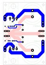
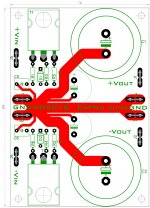
Can you post the two sides separately in pdf or jpeg?Hi X,
Some little exercice......
Marc
Can you post the two sides separately in pdf or jpeg?
Attachments
Thanks Marc. Any hope of stereo CM with all 4 outputs on a 100mmx100mm or is that too tight?
It dépend on 4700µf size so directly related to its voltage rating. With the 70x100mm version (mono version) i be able to put 35mm diam snap in cap so practicaly over 6800µ if want.
Marc
Oh sorry,my fault
I mean in black & white for home etching.")
Hi thimios. I will take a look to provide pdf this weekend.
Marc
Last edited:
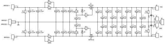
The juma cap multiplier schematic that is in post 95 was what I used on my recent Cubie3 postings. Please look there and a few posts later. In practice I made a few minor changes by using 8.2mF caps for C1-C4, 2.2mF caps for C5-C10 and I changed R3 and R4 to 330 ohms to keep Q1 (T1) and Q2(T2) from ever turning off if the amp was ever in AB mode, as per recommendation from Cirlomanen. Also, I used one PS per channel (dual mono blocs) so it might be slightly overkill. Please note that the IRFP9140 that I pulled from my library had the D and S reversed. In practice, I just soldered the correct wires up, but I will correct the schematic the next time I draw it.
With 1.1A Iq I measured +-36.1VDC on the rails and 0.1mV or less AC on the rails just like xrk971 did. It is less than what my DMM can measure accurately. Like xrk971 says, this circuit is very impressive in measurements and in sound, not to mention its low cost and small size.
With 1.1A Iq I measured +-36.1VDC on the rails and 0.1mV or less AC on the rails just like xrk971 did. It is less than what my DMM can measure accurately. Like xrk971 says, this circuit is very impressive in measurements and in sound, not to mention its low cost and small size.
Oh sorry,my fault
I mean in black & white for home etching.
Is that good for you?
Attachments
normally the bigger can capacitors have 0.4" pin pitch (10.16mm)I am fine with 25mm dia for 4700uF 63v Nichicon caps (12.5mm spacing radial leads).
Test PSU
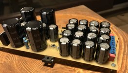
Hi, I have built a PSU free according to the Schematic which X has published in Post No. 95 with the parts I had on the shelf.
Will be tested next days or weekend. Looks good so far, not yet the optimal layout, but will developed. Just a few pictures for the entertainment
regards Olaf
Hi, I have built a PSU free according to the Schematic which X has published in Post No. 95 with the parts I had on the shelf.
Will be tested next days or weekend. Looks good so far, not yet the optimal layout, but will developed. Just a few pictures for the entertainment
regards Olaf
Attachments
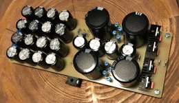
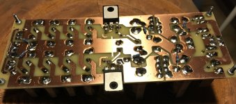


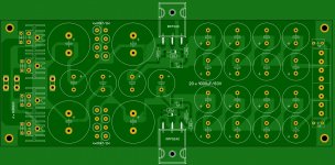
Hi thanks. PCB is released when everything works. Must still install a little cooling for the Fets, the discharge resistors must be finally on the PCB, some LED for check function and test everything. But looks already imposing
75 x 195mm. Maximum length that I can etch at home.
regards Olaf
75 x 195mm. Maximum length that I can etch at home.
regards Olaf
Attachments
Last edited:
Olafk: That looks great...good work. I see you got the pinout correct on the P channel MOSFET so you must have read my post #110, or you used juma's original in his post #1 in Cubie3 thread. I am looking forward to hearing your listening impressions, and I think you will be very pleased as x is and I am.
What is the Voltage drop on this?
Hi thanks. PCB is released when everything works. Must still install a little cooling for the Fets, the discharge resistors must be finally on the PCB, some LED for check function and test everything. But looks already imposing
75 x 195mm. Maximum length that I can etch at home.
regards Olaf
- Home
- Amplifiers
- Power Supplies
- Juma's Easy-Peasy Capacitance Multiplier