If someone wants to take this further, I'll gladly zip up the code and post it. I probably won't do much more with this as a general-purpose modeler, and I'll probably just use it as a GUI for programming the DSP that provides the curvature and attenuation. I'll add the crossover code and get both arrays working, but that would be the end of the modeling effort. My interest is just with full-length multiway line arrays, and this type of modeling doesn't help me much. I still have a lot of code cleanup to do because I didn't start from scratch--I used a diffraction modeler and modified that code as I went along. But I'll clean it up.
There was a 2D version before I switched to the ChartDirector component--see below.
The shading is a function of the x distance along the array. I used Keele's approximation to the Legendre function. There are some approximations to the Bessel function, but I didn't have one handy
Select Case shading_type
Case "None"
shading = 1
Case "Legendre"
shading = 1 + 0.066 * x - 1.8 * x ^ 2 + 0.743 * x ^ 3
Case "Legendre/2"
x = x * 80 / 120
shading = 1 + 0.066 * x - 1.8 * x ^ 2 + 0.743 * x ^ 3
Case "Log"
shading = -Log10(x + 0.1)
Case "Linear"
shading = 1 - x
Case "2:1 linear"
shading = 1 - 0.5 * x
I'm not convinced that vertical off-axis lobing has much correlation to audio quality, especially for full-length line arrays. In order for those lobes to be a problem at "normal" listening positions, the model would need to show that the stereo image gets smeared or distorted in some way, and these models are too simplistic to show that.
To take an extreme example, just click the checkbox on the baffle designer for "open back" in PSD-lite, which is the program I hacked for this line array simulator. Dipoles have some nasty peaks and dips (see below), and John K's dipole spreadsheet show this same behavior, so I know the calculation is correct. Nonetheless, there is something quite satisfying about open back speakers that you wouldn't expect given those wild response curves.
That's why I had stated in an earlier post that we need a better 3D ray-tracing model to really understand how the stereo image is created and how it is affected by the driver topology.
I believe the curve you are showing is not of a reflection related response error, but is of the direct sound as modified by the rear, delayed, dipole response. As such it is not a horizontal or vertical "thing".
Regarding lateral and vertical room reflections, my understanding is that the ear processes lateral and vertical reflections differently. for lateral reflections we use binaural hearing to separate the reflection out from the direct sound. The reflection adds spaciousness or echo depending on the time delay. (These are the teachings of Saint Toole.)
For vertical reflections we don't have the benefit of binaural hearing to separate out floor or ceiling bounces. They end up adding to the direct sound as a frequency response error. In the end you would still have to apply a perceptual smoothing window that would likely show that your high frequency ripple is inaudible. The largest low frequency peak-dip-peak would probably be audible. A similar perceptual filter would need to be applied to the room response.
Attached is a good paper on a large square pattern array (not a line array) that was briefly on the market a few years ago.
The company name was 1...Limited and they showed up at CES with a 96 element array about the same dimensions as a 42 inch TV. On its surface were 96 small elements, each of which had its own DSP and amplifier. The objective of the array was to take a 5.1 signal and create 5 beams of sound that bounced off of appropriate spots in your room to accurately create a 5.1 home theater experience. There was a joystick for setup that would let you steer around each beam until it found an appropriate spot for good reflection back to the listening area from the 5 home theater directions.
I got a private demo and discussion with Tony Hooley, company founder. The array was most effective, I remember hopping out of my seat and crossing over the beam that was aimed at back left. The band edge was very distinct, like stepping in and out of a flashlight beam.
Nobody is doing this currently. I think Pioneer sold the unit under their Elite brand for a while and then it faded away. I would say that Bose (and Yamaha and Sonos) create similar line arrays (not plane arrays) that create multiple directed beams and they are quite effective. The only downside to doing it as a line is that your directed beam becomes an object of rotation, i.e. a ring of radiation rather than a singular beam. In practice this is still useful.
The paper is well worth a read. It contains mostly stuff we know, but it is well presented:
1) Gross array size in any given direction determines how narrow a beam may be formed.
2) We need big arrays to steer low frequency sounds well.
3) Spacing between individual array elements is a key factor. For a uniform array then for output sound waves the array will produce alias beams because of spatial undersampling.
4) non-uniform array locations (arrays were the elements are not regularly spaced) can reduce the alias lobes.
5) Windowing (appodisation) will reduce the intermediate (not the primary) sidelobes. A Gaussian profile will produce a Gaussian beam-shape free of sidelobes, whereas a rectangular profile will produce a sinc function beamshape.
6) Non-planar arrays are possible and advantageous.
Good stuff.
David
Attachments
Okay, starting to play with a log spaced array.
This evolved from the 23 element with numerous drivers omitted to create the logarithmic spacing. Picture the 23 elements with 80 mm spacing. From the center we keep the first (middle) second, not 3rd, yes 4th, 7th, and top. Ditto going down from the middle as the array is symmetrical. Alternatively, viewed from the top you could describe it as using the top, skipping 4 elements, using the 6th, skipping 2, using the 9th, the 11th and twelfth (middle). Again, the bottom half is the same but mirrored.
Remember the idea of log spacing is that you can do a number of steps that (say) double the last spacing and are driven with a next filter that is the previous shape shifted down an octave. The filters and spacing track proportionately for constant directivity. I started with a type 1 array (see post 176 for definitions) with all drivers running full range to low frequencies. This is what you would do if you wanted to use a number of similar sized (say 4") drivers and they all need to help out at the low frequency end. I switched over to a type 2 where each element is a bandpass of approximately constant bandwidth. This would typically have small drivers in the center and progressively larger units towards the top and bottom (similar to a Snell XA). This seemed to optimize better and give more constant directivity. I did presume a tweeter in the central position so that the MTM could be changed to +- 40mm spacing to improve the top most lobe.

Here is the basic filter. You can see the progression of filter frequencies and spacing. Note that I have also added gain progressivly to the outter elements. This would probably naturally occur as the outer elements grew in size.

Directivity (above) is generally uniform from 400 to 10kHz and from -30 to plus 30 degrees. Note that this is from less than an hour of optimizing so it could probably be improved upon.

The filters (above). Although the electrical filters show increased gain for the lower elements this is more to compensate for this model using measurements of smaller full range elements. If I put in more sensible drivers (say progressively sized up to 10" for top and bottom) then the filtering would need less LF gain. I'm still a novice at Vituix.

Response is good. Note that this is not particularly optimized for floor or ceiling bounce cancelation, more for good directivity and lobe free response at any sensible listening height.
This example has 9 elements and 5 "ways" but you could probably achieve good performance with 3 or 4 ways.
Thoughts?
This evolved from the 23 element with numerous drivers omitted to create the logarithmic spacing. Picture the 23 elements with 80 mm spacing. From the center we keep the first (middle) second, not 3rd, yes 4th, 7th, and top. Ditto going down from the middle as the array is symmetrical. Alternatively, viewed from the top you could describe it as using the top, skipping 4 elements, using the 6th, skipping 2, using the 9th, the 11th and twelfth (middle). Again, the bottom half is the same but mirrored.
Remember the idea of log spacing is that you can do a number of steps that (say) double the last spacing and are driven with a next filter that is the previous shape shifted down an octave. The filters and spacing track proportionately for constant directivity. I started with a type 1 array (see post 176 for definitions) with all drivers running full range to low frequencies. This is what you would do if you wanted to use a number of similar sized (say 4") drivers and they all need to help out at the low frequency end. I switched over to a type 2 where each element is a bandpass of approximately constant bandwidth. This would typically have small drivers in the center and progressively larger units towards the top and bottom (similar to a Snell XA). This seemed to optimize better and give more constant directivity. I did presume a tweeter in the central position so that the MTM could be changed to +- 40mm spacing to improve the top most lobe.
Here is the basic filter. You can see the progression of filter frequencies and spacing. Note that I have also added gain progressivly to the outter elements. This would probably naturally occur as the outer elements grew in size.
Directivity (above) is generally uniform from 400 to 10kHz and from -30 to plus 30 degrees. Note that this is from less than an hour of optimizing so it could probably be improved upon.
The filters (above). Although the electrical filters show increased gain for the lower elements this is more to compensate for this model using measurements of smaller full range elements. If I put in more sensible drivers (say progressively sized up to 10" for top and bottom) then the filtering would need less LF gain. I'm still a novice at Vituix.
Response is good. Note that this is not particularly optimized for floor or ceiling bounce cancelation, more for good directivity and lobe free response at any sensible listening height.
This example has 9 elements and 5 "ways" but you could probably achieve good performance with 3 or 4 ways.
Thoughts?
Attached is a good paper on a large square pattern array (not a line array) that was briefly on the market a few years ago.
The company name was 1...Limited and they showed up at CES with a 96 element array about the same dimensions as a 42 inch TV. On its surface were 96 small elements, each of which had its own DSP and amplifier. The objective of the array was to take a 5.1 signal and create 5 beams of sound that bounced off of appropriate spots in your room to accurately create a 5.1 home theater experience. There was a joystick for setup that would let you steer around each beam until it found an appropriate spot for good reflection back to the listening area from the 5 home theater directions.
I got a private demo and discussion with Tony Hooley, company founder. The array was most effective, I remember hopping out of my seat and crossing over the beam that was aimed at back left. The band edge was very distinct, like stepping in and out of a flashlight beam.
Nobody is doing this currently. I think Pioneer sold the unit under their Elite brand for a while and then it faded away. I would say that Bose (and Yamaha and Sonos) create similar line arrays (not plane arrays) that create multiple directed beams and they are quite effective. The only downside to doing it as a line is that your directed beam becomes an object of rotation, i.e. a ring of radiation rather than a singular beam. In practice this is still useful.
The paper is well worth a read. It contains mostly stuff we know, but it is well presented:
1) Gross array size in any given direction determines how narrow a beam may be formed.
2) We need big arrays to steer low frequency sounds well.
3) Spacing between individual array elements is a key factor. For a uniform array then for output sound waves the array will produce alias beams because of spatial undersampling.
4) non-uniform array locations (arrays were the elements are not regularly spaced) can reduce the alias lobes.
5) Windowing (appodisation) will reduce the intermediate (not the primary) sidelobes. A Gaussian profile will produce a Gaussian beam-shape free of sidelobes, whereas a rectangular profile will produce a sinc function beamshape.
6) Non-planar arrays are possible and advantageous.
Good stuff.
David
Modern sound bars are pretty modest. I think the market won't really "tolerate" a soundbar that costs more than the TV it's under, and so the quality has actually devolved in many ways.
The early "sound projectors" from Yamaha were fairly crazy, with something like a hundred drivers in them.
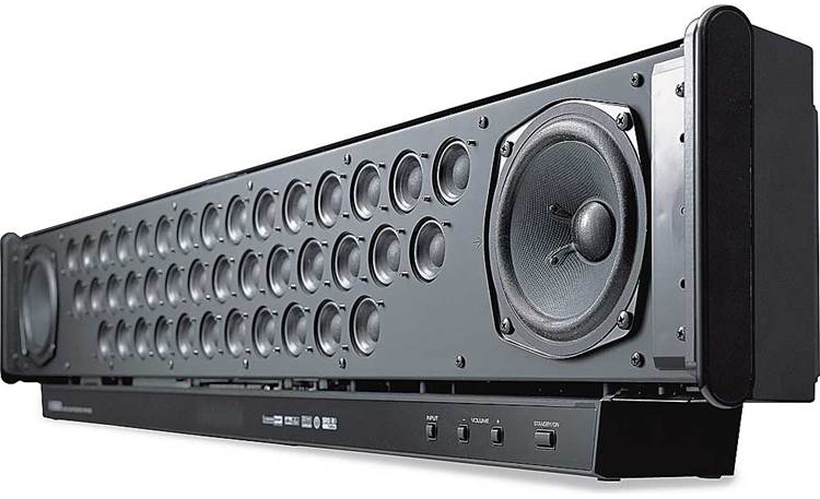
Because they're old and unloved, they're quite affordable. I bought one at a thrift store for about $100. I haven't done much with it.
One of the ideas that I had, is that it might be interesting to basically use the enclosure and the drivers, then add my own amplification and DSP to turn it into a DSP line array. For $100, it's an inexpensive way to get a project started, particularly since building an array enclosure and wiring up all the drivers can be a p.i.t.a.
Having said that, I haven't opened the array up to see what the insides look like.
The 3 lines of "twids" means the Yamaha can create some vertical directivity for surround and Atmos reproduction. As far as I know only Yamaha, Sonos and Bose make any proper steered beam array systems. For Bose the signal is decoded to 3 axes with the array directing energy hard left, right and center. The left and right beams bounce off the side walls for a very wide image. For stereo signals the 3 channels are formed via a steering system similar to Dolby Pro-Logic. That means that rather than mono (centered) components being sent to the left and right axes for virtual center they are isolated and sent to a center firing beam.
I did a number of music optimized prototypes with even higher directivity and 3 axes, plus a full range sub below the array. The music reproduction was in some ways better than any 2 channels system could be in that the stereo spread was wider and the center image was real rather than virtual. With the reflected left and right beams you get sound totally off of any speaker.
I doubt that most audiophiles would be accepting of such a radical approach to stereo but it was in several ways better than any 2 channel, 2 box, system could be.
Just to clarify my description of the log spaced array (a picture is worth...)
This follows the Type 1, Type2 nomenclature as defined a few pages back. Type 1 assumes you have an array of full range elements that will stretch down to the LF region (probably with a sub). Type 2 gives each element a bandpass appropriate to its size and power handling. Upper cutoffs would be the same as used in the individual elements of the type 1's. Directivities would be similar aside from some phase/crossover effects on directivity.
The Type 1 starts with the 80 mm spacing of the 23 locations of the 23 element array (80 mm) and just omits units. Type 2 copies the same center locations although I tightened up the central 3 to 40 mm apart in my simulation.
Thoughts?
Yes,
What does the horizontal Directivity graph look like? (*)
What is the reason behind the crossover on the central tweeter being a second order (with time delay)?
I get it that the spacing is to resemble the use of smaller drivers...
I'm puzzled by the fast growing DI above 3.5 KHz though...(*)
(*)= probably would work better with actual directivity generated per driver of the right picture above.
Horizontal directivity is largely just the directivity of one element (type 1) or of the element in effect at that range of frequencies (type 2).
Note that I cheated here and used the same element directivity for each "way" even though a real design would need a size progression of drivers. That makes no difference for preliminary simulations as long as you can presume that EQ will give your chosen unit whatever bandwidth you might want. NC535 gave me a simulation and I have continued to modify it in Vituix while I learn the program. It was originally based on a TC9FD.
Once you achieve an array with the desired vertical directivity then you can adjust all the elements to be other units as long as you re-equalize to get the same relative response section by section. That is, relative amplitude and phase response, physical location and low and high rolloffs determine the performance of the array. Another unit substituted will have no effect if it can be EQed to the previous sections response.
It may seem like I am taking liberties with the design, but from experience I know what shortcuts I can get away with.
As to directivity above 3000 Hz this is driver directivity. The next units above and below are rolled off enough by that frequency that the directivity is purely that of the driver. Note that sometimes driver directivity helps and other times it hurts. In TV arrays you often rely on the driver to get directivity in the top octaves. At those frequencies it would be difficult to array with drivers as tight together as would be required. This is why a lot of sound bars have units on the left and right end. The array would work up to several kHz and the driver's natural directivity would then take over to keep the left and right beams aimed away from the listener.
2nd order on the tweeter just seems prudent. To avoid lobing you want a low crossover. 2nd order is a minimum to give the unit some power handling and somewhat lower excursion. I have frequently added a waveguide flare to the center unit to increase response at the bottom of the tweeter's range, which also lets you reduce the electrical drive. With second order on this system the phase shift seemed a bit much (based on how well/poorly the response of the sections added) and a little bit of delay got things better in phase and would be in line with incorporating a recessed flare.
David
Last edited:
I guess it could be fun if we would use the directivity of the proper sized drivers for this sim. Maybe even throw in that waveguide.
I was thrown off a bit by the steep rising DI, I have that same TC9 directivity model from nc535 available. Yours had a bit steeper rise than I remembered from my "one driver" model. I later used an Abec simulated driver model of the TC9 with my own rounded enclosure, which had a more gradual shaped directivity horizontally. I guess I got used to seeing that one") .
.
It is good to see this array act much like one single driver, even in phase. Each time with bigger sized drivers taking over lower end duties, it has a lot more potential that way. I never realized that your expanding array had this kind of phase behavior. It's acting much like an 'upgraded' Dunlavy tower speaker with its first order crossovers.
I was thrown off a bit by the steep rising DI, I have that same TC9 directivity model from nc535 available. Yours had a bit steeper rise than I remembered from my "one driver" model. I later used an Abec simulated driver model of the TC9 with my own rounded enclosure, which had a more gradual shaped directivity horizontally. I guess I got used to seeing that one
.It is good to see this array act much like one single driver, even in phase. Each time with bigger sized drivers taking over lower end duties, it has a lot more potential that way. I never realized that your expanding array had this kind of phase behavior. It's acting much like an 'upgraded' Dunlavy tower speaker with its first order crossovers
.I know that "when all you have is a hammer, everything looks like a nail..."
But when I was messing around with this type of array in Vituixcad, it became apparent in a hurry that the mids and woofers need to be closer to the listener.

Basically the delay that's introduced by the low pass filters has to be compensated by bring the mids and woofers closer. When you're done moving the drivers around, it ends up looking like a cross section of a Unity Horn.
If every driver in the array is full range, this isn't an issue. But when you're introducing a low pass at 2khz or 1khz, that's a fairly significant delay.
But when I was messing around with this type of array in Vituixcad, it became apparent in a hurry that the mids and woofers need to be closer to the listener.
Basically the delay that's introduced by the low pass filters has to be compensated by bring the mids and woofers closer. When you're done moving the drivers around, it ends up looking like a cross section of a Unity Horn.
If every driver in the array is full range, this isn't an issue. But when you're introducing a low pass at 2khz or 1khz, that's a fairly significant delay.
Somebody is doing it.. https://holoplot.com/technology/Attached is a good paper on a large square pattern array (not a line array) that was briefly on the market a few years ago.
The company name was 1...Limited and they showed up at CES with a 96 element array about the same dimensions as a 42 inch TV. On its surface were 96 small elements, each of which had its own DSP and amplifier. The objective of the array was to take a 5.1 signal and create 5 beams of sound that bounced off of appropriate spots in your room to accurately create a 5.1 home theater experience. There was a joystick for setup that would let you steer around each beam until it found an appropriate spot for good reflection back to the listening area from the 5 home theater directions.
I got a private demo and discussion with Tony Hooley, company founder. The array was most effective, I remember hopping out of my seat and crossing over the beam that was aimed at back left. The band edge was very distinct, like stepping in and out of a flashlight beam.
Nobody is doing this currently. I think Pioneer sold the unit under their Elite brand for a while and then it faded away. I would say that Bose (and Yamaha and Sonos) create similar line arrays (not plane arrays) that create multiple directed beams and they are quite effective. The only downside to doing it as a line is that your directed beam becomes an object of rotation, i.e. a ring of radiation rather than a singular beam. In practice this is still useful.
The paper is well worth a read. It contains mostly stuff we know, but it is well presented:
1) Gross array size in any given direction determines how narrow a beam may be formed.
2) We need big arrays to steer low frequency sounds well.
3) Spacing between individual array elements is a key factor. For a uniform array then for output sound waves the array will produce alias beams because of spatial undersampling.
4) non-uniform array locations (arrays were the elements are not regularly spaced) can reduce the alias lobes.
5) Windowing (appodisation) will reduce the intermediate (not the primary) sidelobes. A Gaussian profile will produce a Gaussian beam-shape free of sidelobes, whereas a rectangular profile will produce a sinc function beamshape.
6) Non-planar arrays are possible and advantageous.
Good stuff.
David
Could you explain a little more, @Patrick Bateman?
What kind of low pass did you use? I did use low pass filters.. wel not straight forward low pass as I used it as a low shelf before a complete roll off...
(the roll off on the top end actually is a notch filter)

Look at the combined phase here, I don't see the problem you speak of? I'm actually using it to create an even beam vertically.
What kind of low pass did you use? I did use low pass filters.. wel not straight forward low pass as I used it as a low shelf before a complete roll off...
(the roll off on the top end actually is a notch filter)
Look at the combined phase here, I don't see the problem you speak of? I'm actually using it to create an even beam vertically.
Now that is some smart technology!Somebody is doing it.. https://holoplot.com/technology/
Regarding the phase alignment of sections, I have played with low order crossovers and usually get easy alignment. At one time I thought 90 degree blending was the way to go but I don't think there is any one solution.
One way to think of it is that if I lay out my tall symmetrical array and then chop every thing off above the tweeter then I have a nice multi-way tower that needs traditional design tenants: in phase summation of each section. If you achieve that with the bottom half the array then adding the second half must maintain the good phase alignment. You actually have an easier task than that in that the array layout forces the system to have vertical symmetry, although poor summing of the bottom half means lobes due to crossover for the finished array.
My first stab at a sim should by rights have the progressively growing driver depth, hence group delay of the bigger units on the end. Still, the results are no different than any of the real arrays I have done in the past so I don't think I am showing anything unachievable.
There are a lot of variables here and you have to decide what you want. My aim is for smooth polar response and flattest possible response over a wide vertical window. When the crossover points are undetectable then you have achieved something that 99.9% of the other designs out there don't achieve.
- Home
- Loudspeakers
- Multi-Way
- Line arrays. Understanding their behavior through simple modeling