Is this a real driver? The Bessel configuration doesn’t have wider response than the base drivers. It just doesn’t gain directivity as a normal array would.
It's a Dayton ND64-16, but I didn't simulate the narrowing response. Basically I modeled it using only the on-axis data.
Attached is it's polar response
Attachments
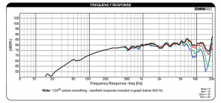
I went outside and measured my ND64-16 on a small baffle to get a set of FRD files.

Here's what ONE driver looks like in VituixCad, when we include polar angles 0-45.

Here's what the 5x5 Bessel Array looks like, when simulated with the polar response of the elements included, at a distance of four meters.

Here's what the 5x5 Bessel Array looks like, when simulated with the polar response of the elements included, at a distance of two meters.
Here's some things to keep in mind with these sims:
I used a baffle that measures 40cm x 40cm. Way too small for a proper measurement. So I think the response above 4000Hz or so is accurate, but I'd take everything below it with a grain of salt. I purely made these measurements and did these sims to see what the impact of driver beaming is on the overall response and performance of the array.
Here's what ONE driver looks like in VituixCad, when we include polar angles 0-45.
Here's what the 5x5 Bessel Array looks like, when simulated with the polar response of the elements included, at a distance of four meters.
Here's what the 5x5 Bessel Array looks like, when simulated with the polar response of the elements included, at a distance of two meters.
Here's some things to keep in mind with these sims:
I used a baffle that measures 40cm x 40cm. Way too small for a proper measurement. So I think the response above 4000Hz or so is accurate, but I'd take everything below it with a grain of salt. I purely made these measurements and did these sims to see what the impact of driver beaming is on the overall response and performance of the array.
Getting back to the 5 element spreadsheet. There are a few things to observe.
If we just use rectangular weighting (each element a strength of 1) then we see a sharper beamwidth as we go up in the number of array elements. There are also n - 1 nulls if we plot one cycle of response (this is essentially a plot from DC to 2 x Nyquist. The "one cycle" requirement is satisfied by observing at a 30 degree angle with a Lambda of 5 cm and a Dee of 10 (more importantly, any 1 to 2 ratio for Lambda to Dee). The 30 degree angle has a sine of 0.5 which cuts the 1 to 2 ratio down to 1 to 1, giving one cycle of plot. (Does that make sense to anyone?)

If we just use rectangular weighting (each element a strength of 1) then we see a sharper beamwidth as we go up in the number of array elements. There are also n - 1 nulls if we plot one cycle of response (this is essentially a plot from DC to 2 x Nyquist. The "one cycle" requirement is satisfied by observing at a 30 degree angle with a Lambda of 5 cm and a Dee of 10 (more importantly, any 1 to 2 ratio for Lambda to Dee). The 30 degree angle has a sine of 0.5 which cuts the 1 to 2 ratio down to 1 to 1, giving one cycle of plot. (Does that make sense to anyone?)
Here is a look at playing with coefficient weightings. The blue curve is just the straight 1 1 1 1 1 weighting. Orange is 0.3 0.7 1.0 0.7 0.3 so it rolls off the outer units a little and gives a little wider bandwidth and a smoother polar at the cost of some level output. Lobe output is the sum of the coefficients so 3 rather than 5 for the rectangular (in this plot the forward response levels are roughly normalized).
The gray plot uses a little bit of negative weighting for the outer 2 elements. -0.1 0.3 1 0.3 -0.1. This really broadens the front lobe, again at the cost of level.

Of course, these only represent the polar curve up to a certain frequency and after that side lobes will form and swing towards the front (aliasing in our DFT analogy.)
David
The gray plot uses a little bit of negative weighting for the outer 2 elements. -0.1 0.3 1 0.3 -0.1. This really broadens the front lobe, again at the cost of level.
Of course, these only represent the polar curve up to a certain frequency and after that side lobes will form and swing towards the front (aliasing in our DFT analogy.)
David
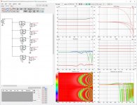
I was intrigued by the gray weights so I entered them into Vituix and looked at response vs distance and the power response curve. the two dashed overlays in the central graph are axial responses at 2m and 4m. The rest of the curves are at 8m. At 80m and 800m, the power response smooths out but I listen to my line arrays at 4m
The Vituix model has 100 mm spacing between drivers. I've linked no directivity files so I get the omni response of point sources.
The Vituix model has 100 mm spacing between drivers. I've linked no directivity files so I get the omni response of point sources.
Attachments
I don't think the Bessel array was primarily mentioned in this thread as being a viable option for home audio?
I think it was mentioned as an interesting variation, what it consists off, technically, and why.
I can't imagine that I would have chosen an array that uses this many drivers but has this little increase in gain from it. Plus it's vertical directivity is much like that of a single driver (at least, once we get far enough out from the array) which also means that the floor and ceiling reflections will have a pretty large influence on it's outcome (sound) in the room itself.
I guess one could say that the most important reason for me to go with arrays was the ability of an array to work with the room.
If we compare the frequency response of a single driver in a room with floor and ceiling reflections factored in,
with an array consisting of the same drivers with the same reflective settings for the floor and ceiling reflections:

Look at the orange "in room" prediction that shows the effect of the floor and ceiling reflections. (*)
One is an array of drivers, the other is a single driver (with similar enough directivity as a Bessel array).
Tell me why you'd want to pay for so many drivers, for very little increase of gain and this kind of directivity.
It may be me, but one of the main advantages of arrays for me is what it does differently from a single driver, not what it does similar.
I want to keep the increase in gain, as well as the way it works with floor and ceiling reflections in a real room.
Others may see it different though. But I haven't seen that many (large) Bessel arrays being tried out, and I'm not surprised by that.
(*) While it may look pretty wild, it's what actually happens in our rooms. It isn't a good representative of what we hear or how we perceive it, but it is happening, in real spaces. If we would apply smoothing, it would look way better") . Both of them actually .
. Both of them actually .
I think it was mentioned as an interesting variation, what it consists off, technically, and why.
I can't imagine that I would have chosen an array that uses this many drivers but has this little increase in gain from it. Plus it's vertical directivity is much like that of a single driver (at least, once we get far enough out from the array) which also means that the floor and ceiling reflections will have a pretty large influence on it's outcome (sound) in the room itself.
I guess one could say that the most important reason for me to go with arrays was the ability of an array to work with the room.
If we compare the frequency response of a single driver in a room with floor and ceiling reflections factored in,
with an array consisting of the same drivers with the same reflective settings for the floor and ceiling reflections:
Look at the orange "in room" prediction that shows the effect of the floor and ceiling reflections. (*)
One is an array of drivers, the other is a single driver (with similar enough directivity as a Bessel array).
Tell me why you'd want to pay for so many drivers, for very little increase of gain and this kind of directivity.
It may be me, but one of the main advantages of arrays for me is what it does differently from a single driver, not what it does similar.
I want to keep the increase in gain, as well as the way it works with floor and ceiling reflections in a real room.
Others may see it different though. But I haven't seen that many (large) Bessel arrays being tried out, and I'm not surprised by that.
(*) While it may look pretty wild, it's what actually happens in our rooms. It isn't a good representative of what we hear or how we perceive it, but it is happening, in real spaces. If we would apply smoothing, it would look way better
. Both of them actually .My weights are linear and only first and fifth are negative.
-0.1 +0.3 1.0 +0.3 -0.1
In dB
-20 -10 0 -10 -20. DB plus polarity of 1 and 5 flipped.
The above example with a 3.5" driver model:
Compared to 5 drivers ran at full power:
Worth it to widen the top end, but we do loose a lot of gain to get there.
I think David is sharing some of the things he learned at [employer name redacted] and is showing us some tricks on how to manipulate the beamwidth and efficiency by tweaking the weights.
I had personally dismissed Bessel arrays as well, but this thread got me giving them a second look.
I'd always know there were some ways to improve them - there are about seven patents to do so. A bunch of them are tricky because they really need a DVC driver but I think we're going to see some "tricks" revealed here.
But even a plain ol' Bessel is attractive when you look at how well the high frequencies perform. High frequencies have always been the Achilles Heel of all the arrays I've done in the past. And the power handling can get fairly ridiculous.
Probably the challenge with conventional Bessel arrays will be that the five unit array seems to perform the best, and so far, I'm not aware of any configurations that use 6+ elements that work well. The six element Bessel is outperformed by the five element Bessel.
But, again, I have a hunch that tweaking the weights and polarities and maybe going two dimensional will work well.
I went digging through the Tekton patents today, hoping they came up with something, but they're nonsensical.
Difficult on the top end, even if you moved far enough back from an array? As one would need to do with a Bessel too.But even a plain ol' Bessel is attractive when you look at how well the high frequencies perform. High frequencies have always been the Achilles Heel of all the arrays I've done in the past. And the power handling can get fairly ridiculous.
I like the lessons, no doubt. As it does make you wonder if we missed something worth while. My interest will remain aimed at controlled vertical directivity and useful gain though. So the first thing that came to mind in the shaded example is: will it work if used only above a certain frequency? To which I do know the answer. I just never went as far as to use negative elements. And yet that is an interesting thought, especially for a shorter array, right @Ethloas ?
Here's a 9 driver Bessel (which ends up using 7 drivers)
But like you said: it doesn't make the results prettier...
Last edited:
Yes, I found out early on that weighted coefficients was a perfect “single frequency “ solution, so not real useful. My paper shows the 23 element long Mac array with a 25 coefficient sin x/x profile. In theory this gives a steep sided “linear phase filter” shaped polar response. It did, at the frequency it was designed for, but at higher frequencies it lobes like any other array.
What was clear was that an ideal profile that scales with wavelength was the answer.
What was clear was that an ideal profile that scales with wavelength was the answer.
A log array David?
Thank you makes me look at an array as a bank of allpass filters. It change perspective.
Where does the introduction of FIR will bring all this?
Could you elaborate on this?
Well,
I'm far behind you (all) about my understanding of arrays so it might be obvious to you, it wasn't to me.
That message blew my mind:
https://www.diyaudio.com/community/...gh-simple-modeling.388279/page-3#post-7076394
From this i understood this:
If you take a 5 elements straight unshaded array, you define your listening point at a given distance in axis of the central driver then the distance from listening position to the center of the two remaining pair of drivers is different wrt the one on axis. Drivers are the same, they replay same signal so what is left as the only remaining variable is phase ( the different distances).
If you change initial listening point it's even more pronounced as the on axis case is particular as there is only two different distance involved ( by pair) rather than the 5 which could happen at worst.
Of course this is the 'woosh woosh' experienced when changing vertical position. And when i want a woosh woosh effect i open a multi cells phaser vst plugin ( or reach an Eventide) in my DAW... which can be a bank of allpass...
Until now i only seen what was happening from a frequency ( filtering) and amplitude ( shading) point of view, it never oocured to me that i forgot phase in it.
From there i see curved array from another view : non shaded or filtered the curved ones could help to compensate for the phase shifts involved by the differents distance. Of course it is theorical as in practice it could be true only on one point, but still.
I can't help myself thinking about Dunlavy's approach too ( or David's 'expanding array') but it is different as signal is filtered ( the drivers are not twins playing same signal anymore).
Hmm. I should have made more math oriented studys!
- Home
- Loudspeakers
- Multi-Way
- Line arrays. Understanding their behavior through simple modeling