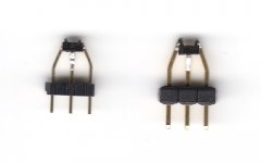
Sticking the SMDs to 50mil pin headers did not work as good as I wanted. Bending the 'legs' outwards for a 100mil grid frequently results in breaking them off from the carrier.
I found another way though: Bending the pins of standard 2.54mm headers inside with needle-nose pliers works a charm! It's a little tricky to hold them in place while soldering, but it's doable.
Please excuse the bad image quality, but I simply used the fladbed scanner (which seriously lacks depth of field) .
.
I found another way though: Bending the pins of standard 2.54mm headers inside with needle-nose pliers works a charm! It's a little tricky to hold them in place while soldering, but it's doable.
Please excuse the bad image quality, but I simply used the fladbed scanner (which seriously lacks depth of field)
.Attachments
Very interesting exercise re.... SIM and 'real' circuit data and performance. SIM gets you in the area... measured is the truth of the matter. Sometimes they differ.
Try next to trim the R values for offset and harmonic distortion. Should help bring the 2H down.
THx-RNMarsh
BTW - I found some brands have more closer N and P type matches than other brands; To only complicate matters further.
Try next to trim the R values for offset and harmonic distortion. Should help bring the 2H down.
THx-RNMarsh
BTW - I found some brands have more closer N and P type matches than other brands; To only complicate matters further.
Last edited:
Any of these pin headers are way too stoff compared to the SOt23.
So whenever you move one of them (e.g. by accident), the SOT23 will have to give.
In any leaded package, one has to build in mechanical compliance (flexibility).
That is why we did those adaptor boards. Not for no reasons.
Plus that the signal path is quite a bit shorter.
Patrick
So whenever you move one of them (e.g. by accident), the SOT23 will have to give.
In any leaded package, one has to build in mechanical compliance (flexibility).
That is why we did those adaptor boards. Not for no reasons.
Plus that the signal path is quite a bit shorter.
Patrick
I could dip them into Epoxy for some stability . They won't be subjected to a lot of movement once they're in their crowded case, though... And I doubt that the signal path is much longer than that of TO-92 devices.
I want to replace the FETs this saturday and then post some more measurement results.
. They won't be subjected to a lot of movement once they're in their crowded case, though... And I doubt that the signal path is much longer than that of TO-92 devices.I want to replace the FETs this saturday and then post some more measurement results.
I could dip them into Epoxy for some stability
The image is a thing of beauty and a testament to your patience.
Getting closer...
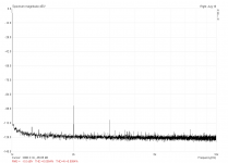
After spending most of the morning with replacement of the FETs and putting back in the original 3k3 resistors, I've now completed the first measurements and noticed that I've missed something. I had changed the 220R (which are 249R originally) to 470R for a reasonable bias current with the other FETs, but didn't remember that while I was in the workshop. So now I'm still running with 470R and a measured bias of ~90mA. A little cooler than before and still on 10.5V instead of 12V, which might be the reason why I still did not reach the optimum performance.
Here are the results: (again 1VRMS into DT-770 80 Ohm)
THD: 0.0055%
THD+N: 0.0092%
k2: -86.43dBV
k3: -108.74dBV
The higher order harmonics are below -120dBV and hide in the noise floor. This looks WAY better than before now! The other channel is within 1dBV of k2 and k3, so they match up pretty well now, too.
These are great results which make me rather happy at the moment.
Of course there's still some room for improvements, but for now I'll actually listen to the amp!
After spending most of the morning with replacement of the FETs and putting back in the original 3k3 resistors, I've now completed the first measurements and noticed that I've missed something
. I had changed the 220R (which are 249R originally) to 470R for a reasonable bias current with the other FETs, but didn't remember that while I was in the workshop. So now I'm still running with 470R and a measured bias of ~90mA. A little cooler than before and still on 10.5V instead of 12V, which might be the reason why I still did not reach the optimum performance.Here are the results: (again 1VRMS into DT-770 80 Ohm)
THD: 0.0055%
THD+N: 0.0092%
k2: -86.43dBV
k3: -108.74dBV
The higher order harmonics are below -120dBV and hide in the noise floor. This looks WAY better than before now! The other channel is within 1dBV of k2 and k3, so they match up pretty well now, too.
These are great results which make me rather happy at the moment
.Of course there's still some room for improvements, but for now I'll actually listen to the amp!
Attachments
Out of curiosity I just measured the substitute FETs that I used before:
N-Ch JFET
Blue-G, Symmetrical Src/Drn
Vgs(off)=-4,09V at Id=0,8µA
Vgs(on)=-1,38V at Id=4,98mA
gfs=2,8mA/V at Id=3,0mA to 5,0mA
Id=9,64mA at Vgs=0,00V and Vds=5,68V
P-Ch JFET
Blue-G, Symmetrical Src/Drn
Vgs(off)=-4,04V at Id=1,0µA
Vgs(on)=-1,54V at Id=5,00mA
gfs=3,4mA/V at Id=3,0mA to 5,0mA
Id=11,51mA at Vgs=0,00V and Vds=4,42V
N-Ch JFET
Blue-G, Symmetrical Src/Drn
Vgs(off)=-4,24V at Id=1,1µA
Vgs(on)=-1,52V at Id=4,99mA
gfs=2,8mA/V at Id=3,0mA to 5,0mA
Id=10,10mA at Vgs=0,00V and Vds=5,38V
P-Ch JFET
Blue-G, Symmetrical Src/Drn
Vgs(off)=-3,66V at Id=1,1µA
Vgs(on)=-1,24V at Id=4,99mA
gfs=3,5mA/V at Id=3,0mA to 5,0mA
Id=10,51mA at Vgs=0,00V and Vds=5,07V
Doesn't look too bad at a first glance, but obviously a bit different than the original devices.
N-Ch JFET
Blue-G, Symmetrical Src/Drn
Vgs(off)=-4,09V at Id=0,8µA
Vgs(on)=-1,38V at Id=4,98mA
gfs=2,8mA/V at Id=3,0mA to 5,0mA
Id=9,64mA at Vgs=0,00V and Vds=5,68V
P-Ch JFET
Blue-G, Symmetrical Src/Drn
Vgs(off)=-4,04V at Id=1,0µA
Vgs(on)=-1,54V at Id=5,00mA
gfs=3,4mA/V at Id=3,0mA to 5,0mA
Id=11,51mA at Vgs=0,00V and Vds=4,42V
N-Ch JFET
Blue-G, Symmetrical Src/Drn
Vgs(off)=-4,24V at Id=1,1µA
Vgs(on)=-1,52V at Id=4,99mA
gfs=2,8mA/V at Id=3,0mA to 5,0mA
Id=10,10mA at Vgs=0,00V and Vds=5,38V
P-Ch JFET
Blue-G, Symmetrical Src/Drn
Vgs(off)=-3,66V at Id=1,1µA
Vgs(on)=-1,24V at Id=4,99mA
gfs=3,5mA/V at Id=3,0mA to 5,0mA
Id=10,51mA at Vgs=0,00V and Vds=5,07V
Doesn't look too bad at a first glance, but obviously a bit different than the original devices.
Member
Joined 2009
Paid Member
I've put together some kits of parts ...
Yes, there is a markup. Mother Theresa is dead.
There's still no schematic for free and somehow this is not a commercial thread ?
As I can see from the datasheet Idss and VgsOff are overlaping for quite wide range for 2n545x and so for 2n546x, in my set of most of devices have Idss about 7-8 mA, so I am wondering If I can use them without any problems...
My chosen devices have many characteristics which must all come together. One is the zero temperature coefficient.... the idle chosen is were it is zero. Thus, no dc offset drift.
THx-RNMarsh
I just found this thread. Your circuit reminds me of a update that you sent to me (delivered by....a mail carrier!!!) in 1981 of your Passive EQ preamp line stage. Good ideas never die! That line stage later got modified with more of your refinements that appeared in TAA in the mid 80's. Yes, I built that variant as well. Anyone on the fence about building this circuit should order the parts now before word gets out and Mouser- DigiKey raises their prices.
-T
hi,
Wow! One of the old timers who was there at the time of creation ---- yes, after developing the topology and on to cascoding it and CCS etc... I have stayed with the basic topology ever since... including power amps etc. In the line stage you refer too.... it behaves as a Current-Mode feedback circuit which has since become very popular with the High-End SOTA circuits.
THx - RNMarsh
OK, I bit the bullet. Linear Audio Issue 3, and the full parts kit with PCB from Jack are in the mail to me.
Need now to size a transformer. Will a 2x 15v 30VA one do?
Not a SS fan, currently using a PP tube amp with my headphones. I am very interested to hear what Richard's amp will do with my LCD-3F cans.
This will be fun. Thanks Richard and Jack.
Need now to size a transformer. Will a 2x 15v 30VA one do?
Not a SS fan, currently using a PP tube amp with my headphones. I am very interested to hear what Richard's amp will do with my LCD-3F cans.
This will be fun. Thanks Richard and Jack.
Need now to size a transformer. Will a 2x 15v 30VA one do?
Jameco has a Meanwell DC-DC Converter which requires 9 to 18Vin to +/-12V out. The switching noise is pretty modest. If you intend to use it, bypass the converter with 100nF ceramics at the converter, and at the 220uF caps on the board.
- Home
- Amplifiers
- Headphone Systems
- Marsh headphone amp from Linear Audio