I can't edit my earlier post so let me amend it here:
Regarding the mic angled vs not angled conclusion, I will need to revisit my assessment.
These results show higher frequency combing. I can't say how much of this is the result of the mic holder causing reflections or if this is literally all caused by the mic being angled. I would need to remeasure with foam or something that wouldn't cause a reflection to hold the mic at an angle to know for sure. I will need to consider this a bit more. What I've read is that aiming the mic down is best to get it on the same plane but I worry about the reflection from the holder so I will try to come up with a way to do this. Maybe something as simple as a thin block wedge where there is no empty space and therefore no chance for a reflection. If I re-test this aspect I will post back the results.
All this stuff is well above my pay grade but after reading a few pages it all seems about reflections and how they affect/skew measurement results... thinking out aloud but,
What if you faced the speaker upwards to the sky and hang the mic above from a couple of stands with a fishing line strung between them on a "non-windy" day? Surely this would minimise reflections with nothing to bounce off?
A bit like Ozzy Ozboure Barking at the moon
What if you faced the speaker upwards to the sky and hang the mic above from a couple of stands with a fishing line strung between them on a "non-windy" day? Surely this would minimise reflections with nothing to bounce off?
A bit like Ozzy Ozboure Barking at the moon
The various measurement setups are interesting to explore and the info will be useful for rigorous approaches. However, in practice any setup has its deficiencies. For the purpose of review info, establishing a reference method with disclosure, is really all that is needed. Also, by its nature, measurement does not invoke the heating effects of program material. In my view, the best methods are those that can produce repeatable data within 0.5dB. An outdoor environment may be challenging in this regard.
I also don't understand how LF performance can be modeled from TS parameters alone. Cabinet treatment and design determines how much energy from the rear wall gets reflected back through the cone. This energy can be measured by using non-standard measuring distances and is not always manifest in typical data.
I also don't understand how LF performance can be modeled from TS parameters alone. Cabinet treatment and design determines how much energy from the rear wall gets reflected back through the cone. This energy can be measured by using non-standard measuring distances and is not always manifest in typical data.
Please, allow me to vent...
Yesterday the weather was nice. No wind. The neighborhood was quiet. So, I set out to measure the S400 and get it done. I ran horizontal and vertical measurements. About 30 total measurements.
But, I made a stupid mistake. Given that it seemed the "mic angled down" measurements were a close match to what was expected, I decided to go this route but I made a foam "shroud" to prevent any reflections from the mic holder altering the result. Like so:
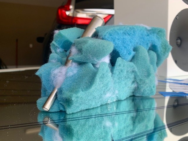
My mistake was: I didn't test the 'shroud' first. So, I completed all of these measurements, went and looked at the results and saw this:
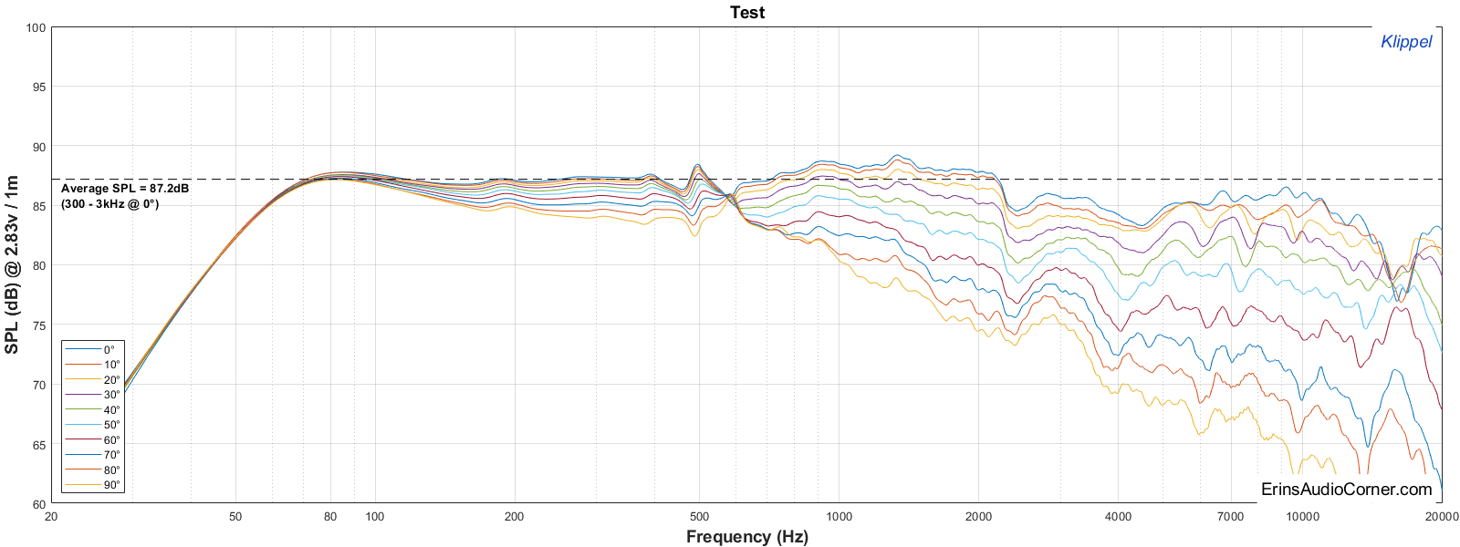
Man, that is a LOVELY sight to see. Look at that high resolution! Oh, but wait.... Above 3kHz the data is junk!!!! Sonuva!!!!...
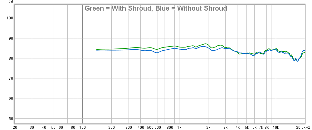
So, today I measured in the garage (ground plane, 2 meters, gated to about 8ms): 1) with shroud and 2) without shroud. The "with shroud" reduces output above 3kHz by about 1-1.5dB.
I am about to lose my ever-loving mind here.

I really want accurate data out of a single measurement (ie, no 'splicing' or 'blending'). My issue with splicing is it requires nearfield measurements of each woofer/vent and results in a nearfield bump. My issue with blending is it requires additional modeling that would also increase lead time. Plus, there's the concern that you really can't just assume a NF mic measurement of the different sources will behave the same off-axis; especially when you don't have high resolution due to the window size. And then imagine splicing a single NF set of measurements with multiple off-axis measurements. But from this little bookshelf alone I can already tell you the polars wouldn't be correct and the resolution/accuracy in the midrange would also suffer. Proof? Look at my above set of horizontal measurements; see the split begins about 100-200hz? On-axis NF + FF stitching won't show you that. I want that data.
A single ground plane measurement would give me data down to < 30Hz; that's resolution better than some anechoic chambers. It also means no need to blend or splice. That also means there is less chance for error in complicated enclosures where there are different sound sources on different sides of a large enclosure (ie, woofer on front, vent on back). Cons of the ground plane measurement are simply that it is outside and I have to contend with weather and neighborhood kids. Not to mention having to walk 40 feet to go turn the speaker (and I have played with different automated designs but they all elevate the speaker on a platform which only alters the data).
I have one more thing I want to try. If that is no bueno I'm gonna have to really think this over and consider the pros/cons of the above. I keep falling back to the driveway ground plane measurement but again, that has its own set of cons. I think my only solace in all of this is that "if it were easy, everyone would do it". I just didn't realize how much legwork I was going to be putting in to get confidence in my measurements. I almost wish I didn't know what the data should look like. I tell ya', ignorance is bliss, folks.
If any of you think I am being too complicated about this: I am. I know it. But that's because I want this data to be accurate. I could easily do some 5ms windows in my garage, do some NF measurements, slap 'em together and call it a day. And that's not a knock against others who don't have a choice but to do that. It is simply that I know I can do better... but how badly do I want to do better is the real question. Hey, if nothing else, maybe I can help you guys avoid the same mistakes I am making.

/rant
Yesterday the weather was nice. No wind. The neighborhood was quiet. So, I set out to measure the S400 and get it done. I ran horizontal and vertical measurements. About 30 total measurements.
But, I made a stupid mistake. Given that it seemed the "mic angled down" measurements were a close match to what was expected, I decided to go this route but I made a foam "shroud" to prevent any reflections from the mic holder altering the result. Like so:
My mistake was: I didn't test the 'shroud' first. So, I completed all of these measurements, went and looked at the results and saw this:
Man, that is a LOVELY sight to see. Look at that high resolution! Oh, but wait.... Above 3kHz the data is junk!!!! Sonuva!!!!...
So, today I measured in the garage (ground plane, 2 meters, gated to about 8ms): 1) with shroud and 2) without shroud. The "with shroud" reduces output above 3kHz by about 1-1.5dB.
I am about to lose my ever-loving mind here.
I really want accurate data out of a single measurement (ie, no 'splicing' or 'blending'). My issue with splicing is it requires nearfield measurements of each woofer/vent and results in a nearfield bump. My issue with blending is it requires additional modeling that would also increase lead time. Plus, there's the concern that you really can't just assume a NF mic measurement of the different sources will behave the same off-axis; especially when you don't have high resolution due to the window size. And then imagine splicing a single NF set of measurements with multiple off-axis measurements. But from this little bookshelf alone I can already tell you the polars wouldn't be correct and the resolution/accuracy in the midrange would also suffer. Proof? Look at my above set of horizontal measurements; see the split begins about 100-200hz? On-axis NF + FF stitching won't show you that. I want that data.
A single ground plane measurement would give me data down to < 30Hz; that's resolution better than some anechoic chambers. It also means no need to blend or splice. That also means there is less chance for error in complicated enclosures where there are different sound sources on different sides of a large enclosure (ie, woofer on front, vent on back). Cons of the ground plane measurement are simply that it is outside and I have to contend with weather and neighborhood kids. Not to mention having to walk 40 feet to go turn the speaker (and I have played with different automated designs but they all elevate the speaker on a platform which only alters the data).
I have one more thing I want to try. If that is no bueno I'm gonna have to really think this over and consider the pros/cons of the above. I keep falling back to the driveway ground plane measurement but again, that has its own set of cons. I think my only solace in all of this is that "if it were easy, everyone would do it". I just didn't realize how much legwork I was going to be putting in to get confidence in my measurements. I almost wish I didn't know what the data should look like. I tell ya', ignorance is bliss, folks.
If any of you think I am being too complicated about this: I am. I know it. But that's because I want this data to be accurate. I could easily do some 5ms windows in my garage, do some NF measurements, slap 'em together and call it a day. And that's not a knock against others who don't have a choice but to do that. It is simply that I know I can do better... but how badly do I want to do better is the real question. Hey, if nothing else, maybe I can help you guys avoid the same mistakes I am making.
/rant
Last edited:
"Hey, if nothing else, maybe I can help you guys avoid the same mistakes I am making."
That, you already did; thank you for it. And, Fluid, thanks for the explanation. It is really appreciated; I'm just sorry I couldn't reply sooner. Covid-19 or not, I still have a lot of work to do, and don't come here as often as I would like.
DF
That, you already did; thank you for it. And, Fluid, thanks for the explanation. It is really appreciated; I'm just sorry I couldn't reply sooner. Covid-19 or not, I still have a lot of work to do, and don't come here as often as I would like.
DF
Nothing wrong with wanting to get accurate dataIf any of you think I am being too complicated about this: I am. I know it. But that's because I want this data to be accurate.
No problemAnd, Fluid, thanks for the explanation. It is really appreciated
Thank you very much Erin et al. for this thread! Measuring loudspeaker output is really really difficult! Every "system" has flaws.
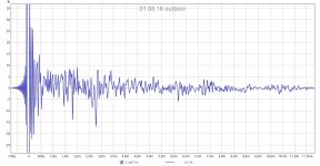
Perhaps spliced combination of groundplane up to 500-1kHz and on high stand would be best. But naturally single fullrange measurements would be faster to perform... Impulse response will show all reflections easily, and reveals best how different measurements are.
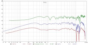
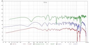
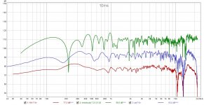
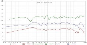
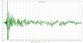
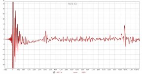
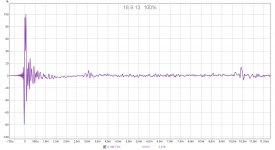
Above 1khz isn't easy either. Here my measurements with the same mic, different evironment and distance. Also on-axis line was with eyes only. The speaker is diy with co-axial SEAS T18 with aluminium tweeter. I have no idea which of these is the right one... The purple one was done outdoors at 1,5m, others indoors.
Perhaps spliced combination of groundplane up to 500-1kHz and on high stand would be best. But naturally single fullrange measurements would be faster to perform... Impulse response will show all reflections easily, and reveals best how different measurements are.
Above 1khz isn't easy either. Here my measurements with the same mic, different evironment and distance. Also on-axis line was with eyes only. The speaker is diy with co-axial SEAS T18 with aluminium tweeter. I have no idea which of these is the right one... The purple one was done outdoors at 1,5m, others indoors.
Attachments
-
 aw-7 0deg 3ms nosmo.jpg155.8 KB · Views: 97
 -
 aw-7 0deg 6ms nosmo.jpg169.6 KB · Views: 94
 -
 aw-7 0deg 10ms nosmo.jpg183.1 KB · Views: 90
 -
 aw-7 0deg 6ms 112.jpg150.5 KB · Views: 89
 -
 aw-7 odeg imp 010816.jpg157.7 KB · Views: 90
 -
 aw-7 odeg imp 070616.jpg166.7 KB · Views: 90
 -
 aw-7 odeg imp 160913.jpg153.3 KB · Views: 101
Last edited:
Please notice that impulse displays show only 30% of the signal peak.
But yes first ms is hashy. Mic was taped on a camera tripod. Also co-axials have those interferences making dips and peaks 10-20kHz
Red impulse with 100%
But yes first ms is hashy. Mic was taped on a camera tripod. Also co-axials have those interferences making dips and peaks 10-20kHz
Red impulse with 100%
Attachments
Last edited:
At this point I am pretty sure most who were paying attention have probably "checked out" at this point in the whole "how am I going to measure speakers" discussion but I'm going to make one final post on the topic because I had to feed my own curiosity...
To recap where my mental state is:
Driveway ground plane measurements look quite good. They make life a bit easier because there is no need to stitch. But they do come with cons (I'll cover this later). The only issue with GP in the driveway is neighborhood kids and other random things causing distractions when I am measuring. The backyard would be ideal but as I discovered in earlier tests, the grass is too absorbent and even a 2x8 foot section of plywood wasn't enough. I either need a large concrete pad or some other area of reflective surface. As a "last ditch" effort of trying to make the backyard GP measurements work, yesterday I went to Lowe's and purchased 3 large sheets of plywood. The idea was I would try them laying in the backyard as a "large, flat, reflective surface". I could have purchased more but I thought if 3 isn't sufficient to do what I need I might as well just stick with the driveway if I am going to do GP measurements.
First I had to wet the sheets down because they were bent. I learned this trick from my skatepark/ramp building days. Wet the concave side, lay it on the concave side. I let it set overnight. This morning they were all mostly flat.
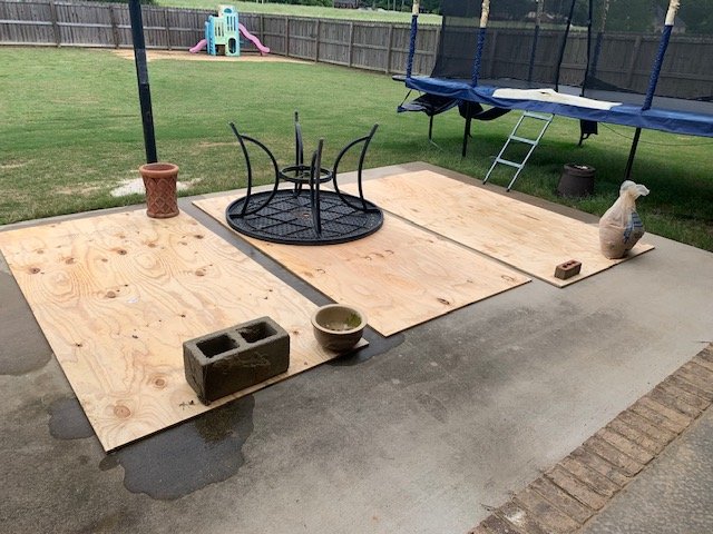
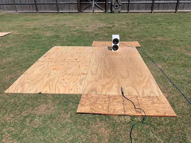
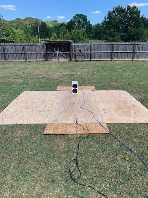
Then it was on to testing. I tried ALL sorts of configurations between measuring longways and sideways. Here's some random photos...
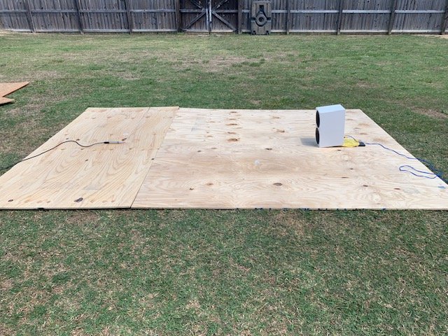
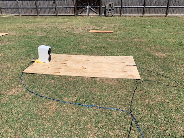
But, I'll spare you the results of EVERYTHING and get to the point more quickly:
First up, let's look at the data from placing the mic on a single sheet of plywood vs the "bare ground" I took a couple weeks ago vs the (windowed) ground plane measurement I conducted in my garage:
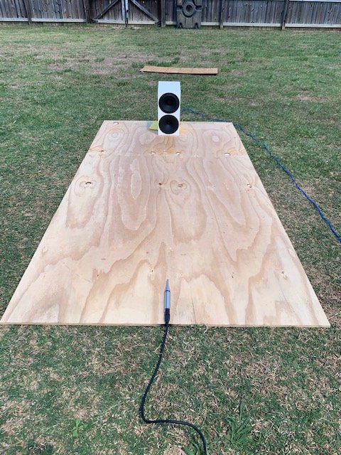
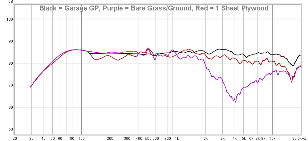
As you can see, there is some improvement in the high frequencies when using the single plywood sheet compared to the bare ground measurements. Notably, with the plywood the HF response no longer has a sharp dip it did in bare grass. But, the plywood measurement shows a dip between 100-300hz and compared to the garage GP mesurement the HF response is still not what it should be; down by about 2-3dB above 1kHz.
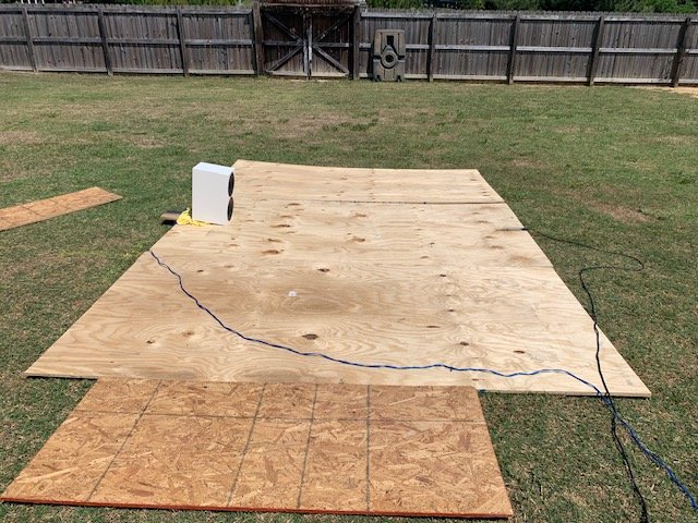
What happens when I add a small piece of OSB behind the mic (Purple) and then as another test I add a small sheet behind the microphone as well (orange)?
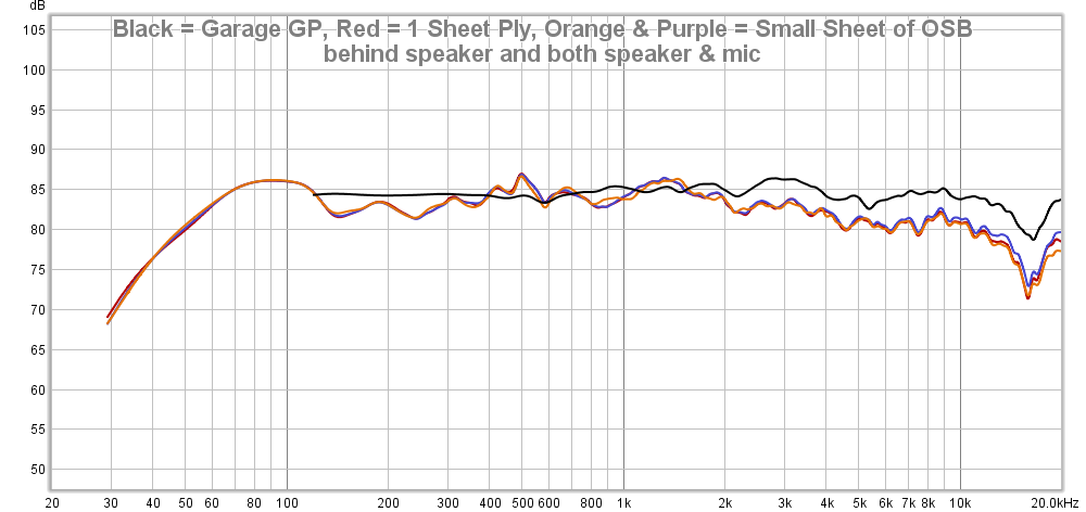
Practically zero difference when placing the small section of OSB behind the speaker and then both the speaker and the mic.
No point wasting time doing that. But, further results will all have both these scrap OSB pieces in the measurement.
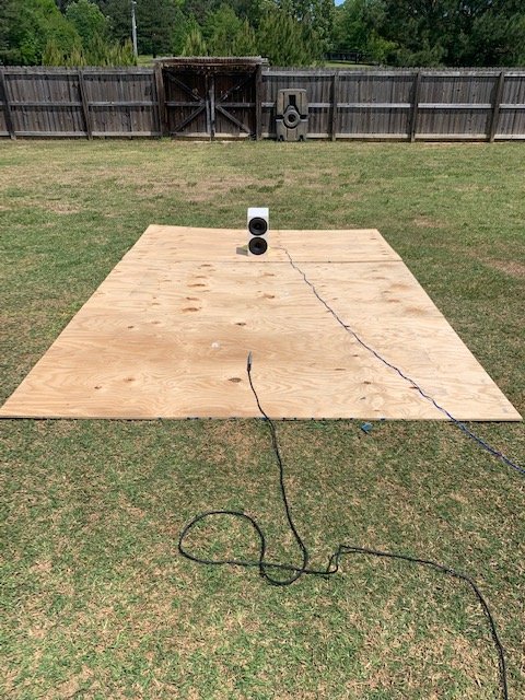
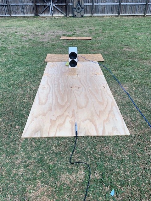
Okay, so what happens when I add a second sheet of plywood to the side (brown)?
What about adding a 3rd piece of plywood to the side, with the speaker/mic in the middle (green)?
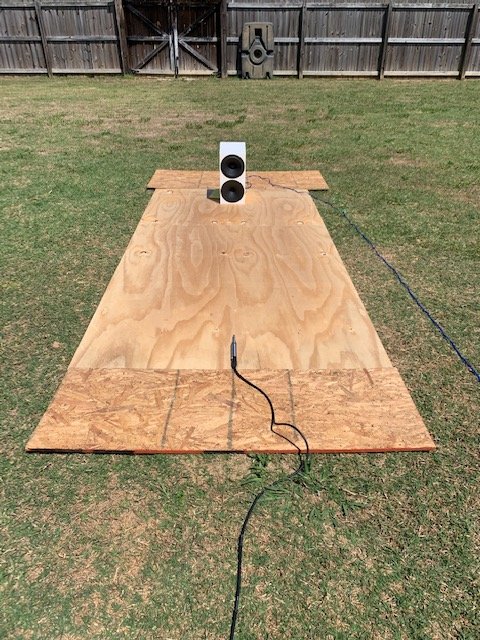
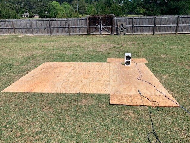
What about shifting the speaker/mic off to one piece of plywood (purple)?
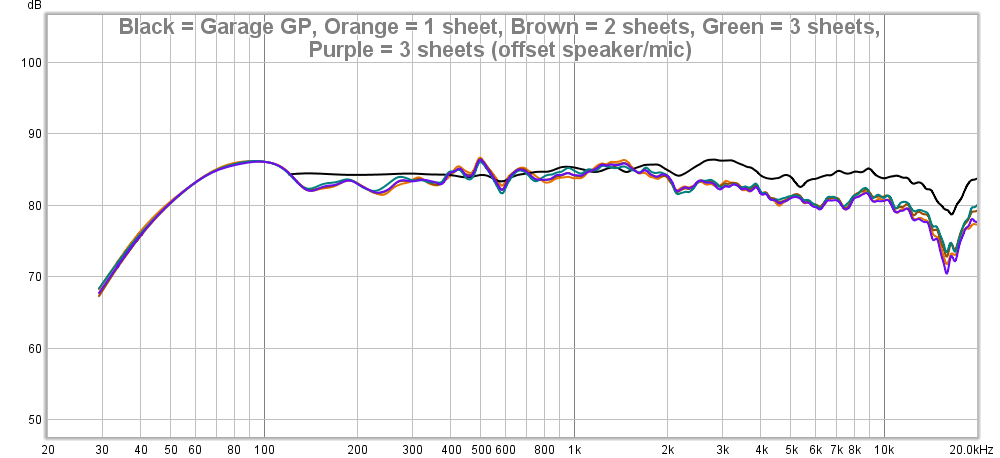
Moral of this story:
Don't bother wasting money on plywood thinking if you create enough surface area you'll get accurate results. Maybe if you buy a LOT of plywood. Maybe. But then you have to take it up and put it down for test. If you want to do ground plane measurements you need a LARGE, FLAT, concrete area. I wasted $60 on this experiment but at least I know now. So, let me save you money: Don't waste your time doing what I did with the plywood. As you can see it doesn't fix the issue entirely.
(now, maybe I could 'calibrate' the measurement for this plywood but I don't trust that.)
I considered buying the OSB with the radiant barrier to see if it would help with reflection and maybe fix the HF. I also considered buying a large sheet (4x8 foot) of the dry-erase board sold at Lowe's. Then there's the trough between 100-300Hz that *I think* may be fixed by more surface area. But I am so incredibly broke with having spent all this money on "this vs that"... I am literally selling old, beloved video games (NES nostalgia rules!) and anything else I don't need at this point to help replenish my bank account after all of this stuff I've bought the last month.
To recap where my mental state is:
Driveway ground plane measurements look quite good. They make life a bit easier because there is no need to stitch. But they do come with cons (I'll cover this later). The only issue with GP in the driveway is neighborhood kids and other random things causing distractions when I am measuring. The backyard would be ideal but as I discovered in earlier tests, the grass is too absorbent and even a 2x8 foot section of plywood wasn't enough. I either need a large concrete pad or some other area of reflective surface. As a "last ditch" effort of trying to make the backyard GP measurements work, yesterday I went to Lowe's and purchased 3 large sheets of plywood. The idea was I would try them laying in the backyard as a "large, flat, reflective surface". I could have purchased more but I thought if 3 isn't sufficient to do what I need I might as well just stick with the driveway if I am going to do GP measurements.
First I had to wet the sheets down because they were bent. I learned this trick from my skatepark/ramp building days. Wet the concave side, lay it on the concave side. I let it set overnight. This morning they were all mostly flat.
Then it was on to testing. I tried ALL sorts of configurations between measuring longways and sideways. Here's some random photos...
But, I'll spare you the results of EVERYTHING and get to the point more quickly:
First up, let's look at the data from placing the mic on a single sheet of plywood vs the "bare ground" I took a couple weeks ago vs the (windowed) ground plane measurement I conducted in my garage:
As you can see, there is some improvement in the high frequencies when using the single plywood sheet compared to the bare ground measurements. Notably, with the plywood the HF response no longer has a sharp dip it did in bare grass. But, the plywood measurement shows a dip between 100-300hz and compared to the garage GP mesurement the HF response is still not what it should be; down by about 2-3dB above 1kHz.
What happens when I add a small piece of OSB behind the mic (Purple) and then as another test I add a small sheet behind the microphone as well (orange)?
Practically zero difference when placing the small section of OSB behind the speaker and then both the speaker and the mic.
No point wasting time doing that. But, further results will all have both these scrap OSB pieces in the measurement.
Okay, so what happens when I add a second sheet of plywood to the side (brown)?
What about adding a 3rd piece of plywood to the side, with the speaker/mic in the middle (green)?
What about shifting the speaker/mic off to one piece of plywood (purple)?
Moral of this story:
Don't bother wasting money on plywood thinking if you create enough surface area you'll get accurate results. Maybe if you buy a LOT of plywood. Maybe. But then you have to take it up and put it down for test. If you want to do ground plane measurements you need a LARGE, FLAT, concrete area. I wasted $60 on this experiment but at least I know now. So, let me save you money: Don't waste your time doing what I did with the plywood. As you can see it doesn't fix the issue entirely.
(now, maybe I could 'calibrate' the measurement for this plywood but I don't trust that.)
I considered buying the OSB with the radiant barrier to see if it would help with reflection and maybe fix the HF. I also considered buying a large sheet (4x8 foot) of the dry-erase board sold at Lowe's. Then there's the trough between 100-300Hz that *I think* may be fixed by more surface area. But I am so incredibly broke with having spent all this money on "this vs that"... I am literally selling old, beloved video games (NES nostalgia rules!) and anything else I don't need at this point to help replenish my bank account after all of this stuff I've bought the last month.
Last edited:
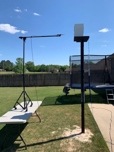
Since I was in my backyard I thought ... might as well go ahead and throw the speaker back up on the platform and test there to see how the ground plane garage measurement compares to the 4pi "free space" measurement at 36 inches. After adjusting level differences (36 inch vs 2 meter/GP), you can see the two are practically identical!
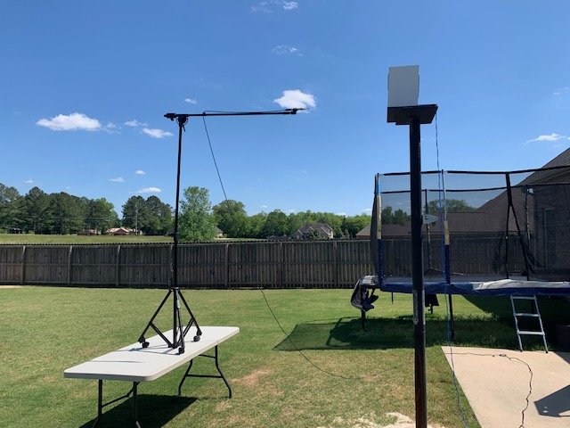
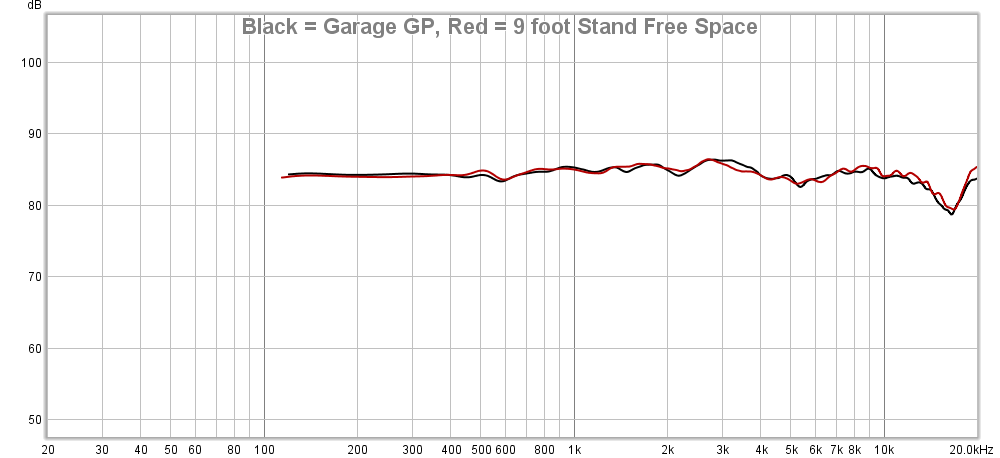
And then I took another measurement from 12 inches:
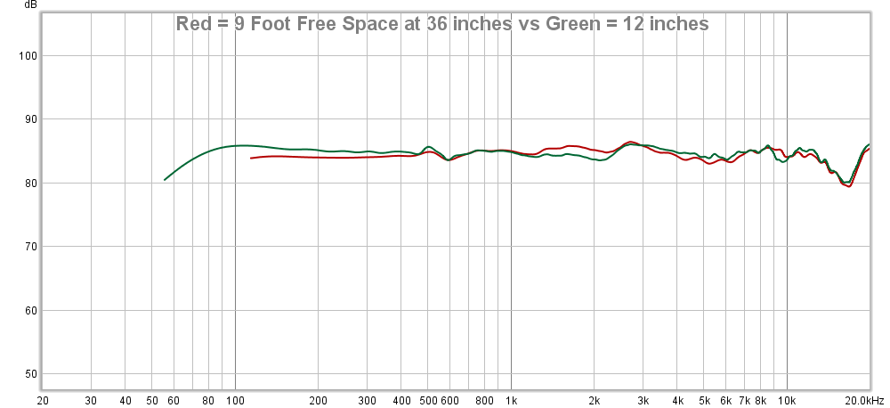
The nearfield gives a bit better resolution on the lower end at the *potential sacrifice of the accuracy in the 1-2kHz region.
*This could be aiming; I wasn't being critical about being "dead on" to the tweeter in these tests; just getting close enough to see what difference the trend showed, if any.
Moral of this story:
Ground Plane measurements can, indeed, yield highly accurate results identical to their 4-pi counterpart. And it is a whole lot easier to place a speaker on the ground than it is to hoist it 8+ feet in the air.
And then I took another measurement from 12 inches:
The nearfield gives a bit better resolution on the lower end at the *potential sacrifice of the accuracy in the 1-2kHz region.
*This could be aiming; I wasn't being critical about being "dead on" to the tweeter in these tests; just getting close enough to see what difference the trend showed, if any.
Moral of this story:
Ground Plane measurements can, indeed, yield highly accurate results identical to their 4-pi counterpart. And it is a whole lot easier to place a speaker on the ground than it is to hoist it 8+ feet in the air.
At this point I have the following options if I want high resolution and accuracy:
If I want to avoid merging NF with FF measurements then I go with the ground plane measurements in the driveway and just deal with the heat, the neighbors and other environmental factors.
If I want to avoid the environmental factors, I can use the NF/FF merging using ground-plane measurements in my garage for farfield and for nearfield, experiment with outdoor ground plane for low frequency if I am concerned about external noise influencing the result or use the standard close-mic method. I prefer ground plane to 4-pi because I've already shown it to be as accurate and raising the speaker up to 8+ feet doesn't seem to make much sense anymore when I know I can get just as good results by using the ground plane measurement in my garage. I still want to experiment with how to build a rotating platform that doesn't corrupt the data (the same way baffle step effects a speaker design) but I may have to wait until I sell a few things before I can make another trip to the hardware store.
Now, that said, I don't have to conduct ALL my tests in the same fashion. I could conduct some outdoors but if, for example, I wanted to test a speaker when it was freezing cold outside then I would just test in the garage and navigate the merging challenges.
That's where my head is at at this moment. Let's see how long this sticks. What's the over/under for a single night?
Of course, as overwhelmed as I feel doing this stuff, sometimes I feel like I'm just gonna quit.
Last edited:
It always amazes me to see what one person can do when he sets his mind to it.
It's a rough spot to be in.


After sleeping on this I have decided that merging Low Frequency with High Frequency data (similar to NF/FF merging) is the only way I will be able to do this and provide the data to the accuracy I desire in most cases. That means I will have to measure ground plane both indoors and outdoors. (If I happen to have really nice weather conditions where the outdoors measurement results in the same HF response as indoors then I won't bother at all with splicing).
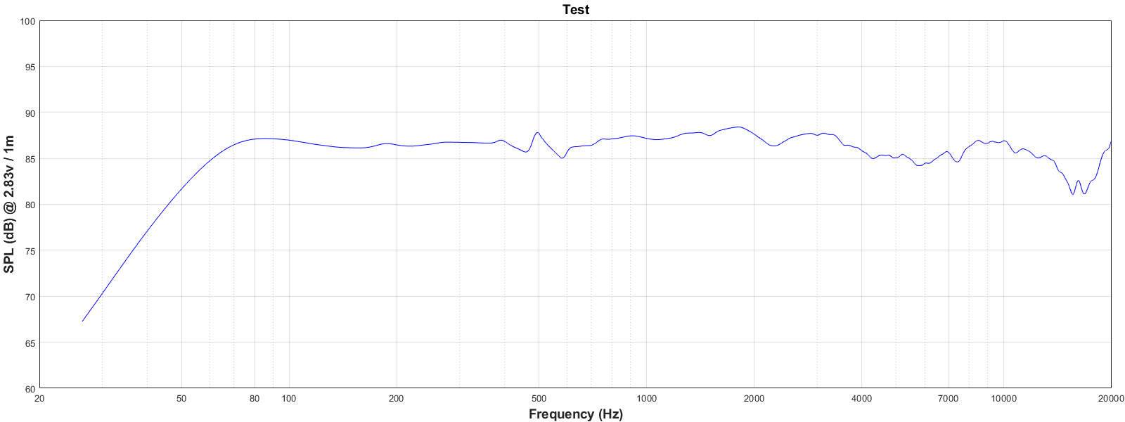
Now, there are options to merge the data: using the various software available (virtuixCAD, DIY'rs excel sheets) or I can use Klippel's script. However, this all requires me to merge one at a time. To get vertical and horizontal data, that's merging about 60 files down to about 30. That would be agonizing (and most importantly, prone to accidental error). So, I wrote a script in Matlab to do a "hard splice" in a batch. I provide it all the files, tell it where I want the splice to be and it calculates the delta and makes the low frequency graph merge to the upper frequency; same premise as NF/FF merging. I am ignoring phase for this aspect and focusing solely on the resultant FR. The plan is to measure all angles... I'll have to do it twice: in the garage for mid/upper and outdoors for lower. But once I do that, I can load the FR files as txt and my script will take care of the rest and throw them all on a plot. I have another version for a "soft splice" which will try to blend data points but for now the hard splice method works well as long as I choose a frequency where there is good consistency between trends (and I have the data resolution to support it). Anyway, here's an example for a single on-axis response, combining the response in the midrange area.
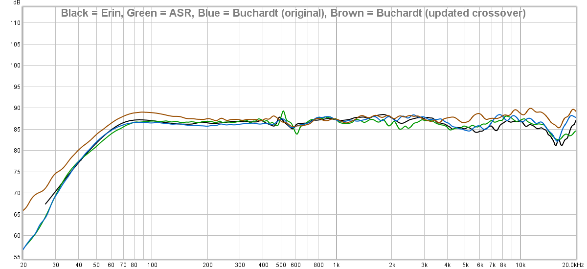
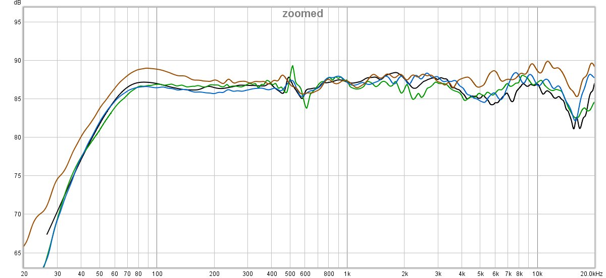
For the time being I have provided the output of my combined LF/HF merged data with that of ASR's as well as Buchardt's NFS data. My result is right in between theirs. And, therefore, IMHO, certainly acceptable. Take note that I have provided two of Buchardt's NFS results: one is "original" which was measured before they implemented a slight crossover modification and the other is the "updated" which was measured more recently with the modification in place.
I still need to resolve the turntable aspect to save me time of turning the DUT manually. Making the center of rotation at the baffle creates some challenges when you have a turntable that is built with the platform an inch or two above the ground; you get a baffle step effect from the lifted platform in addition to reflection from the platform itself. I've got a couple ideas to try. I'll post on that later. If all else fails, I'll just use a piece of cardboard and turn the DUT manually as I did earlier this week.
At any rate, I'm making forward progress. Yay!
Now, there are options to merge the data: using the various software available (virtuixCAD, DIY'rs excel sheets) or I can use Klippel's script. However, this all requires me to merge one at a time. To get vertical and horizontal data, that's merging about 60 files down to about 30. That would be agonizing (and most importantly, prone to accidental error). So, I wrote a script in Matlab to do a "hard splice" in a batch. I provide it all the files, tell it where I want the splice to be and it calculates the delta and makes the low frequency graph merge to the upper frequency; same premise as NF/FF merging. I am ignoring phase for this aspect and focusing solely on the resultant FR. The plan is to measure all angles... I'll have to do it twice: in the garage for mid/upper and outdoors for lower. But once I do that, I can load the FR files as txt and my script will take care of the rest and throw them all on a plot. I have another version for a "soft splice" which will try to blend data points but for now the hard splice method works well as long as I choose a frequency where there is good consistency between trends (and I have the data resolution to support it). Anyway, here's an example for a single on-axis response, combining the response in the midrange area.
For the time being I have provided the output of my combined LF/HF merged data with that of ASR's as well as Buchardt's NFS data. My result is right in between theirs. And, therefore, IMHO, certainly acceptable. Take note that I have provided two of Buchardt's NFS results: one is "original" which was measured before they implemented a slight crossover modification and the other is the "updated" which was measured more recently with the modification in place.
I still need to resolve the turntable aspect to save me time of turning the DUT manually. Making the center of rotation at the baffle creates some challenges when you have a turntable that is built with the platform an inch or two above the ground; you get a baffle step effect from the lifted platform in addition to reflection from the platform itself. I've got a couple ideas to try. I'll post on that later. If all else fails, I'll just use a piece of cardboard and turn the DUT manually as I did earlier this week.
At any rate, I'm making forward progress. Yay!
Last edited:
- Home
- Loudspeakers
- Multi-Way
- Measuring Response: How close is "close enough" to anechoic?