It was asked on DIYA so I am sharing it here...
Yes. But to reiterate, it makes more sense to perform an indoors ground plane measurement instead of the speaker-on-a-stand measurement for the reasons I listed previously. At least for me.
The DUT I have been using is one with a passive radiator so I cannot perform the MIB test. However, I had previously captured nearfield response of both the woofer and the PR.
FWIW, I am using the sd of these drivers (as they appear to be the same ones used in the Buchardt S400, with assumed differences in electro-mechanical properties; however the physial dimensions are almost certainly the exact same):
SB Acoustics SB15SFCR39-8 5x8" Paper Cone Woofer
SB Acoustics SB15NBAC30-4 5" Black Aluminum Cone Mid-bass
With the above stated, the nearfield method has a maximum frequency accuracy dictated by the size (as discussed in the above audioexpress link). The 5" woofer is limited to about 980hz and the 5x8 inch passive radiator I will limit to the 8 inch dimension and therefore is invalid above about 600hz. Just spit-balling here; not using the actual effective radius. But it's close enough.
... On with the results ...
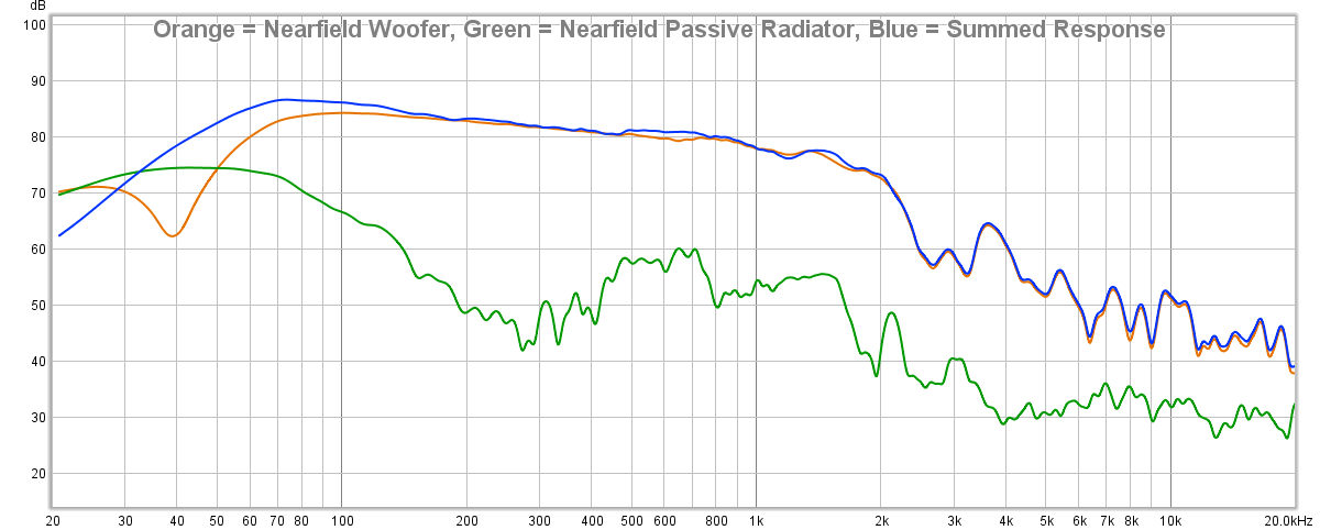
As you may know, when capturing near-field data it's hard to get the exact same level relative to distance of mic from cone and therefore the result is usually "eyeballed" to overlay them together, by using the lowest frequencies. I have done that below. What you see below is:
Woofer Nearfield (orange)
Passive Radiator Nearfield (green)
Summed Nearfield Response of the Woofer + PR (blue)
*Note the y-axis scale is 10dB. Using 5dB is too hard to read.
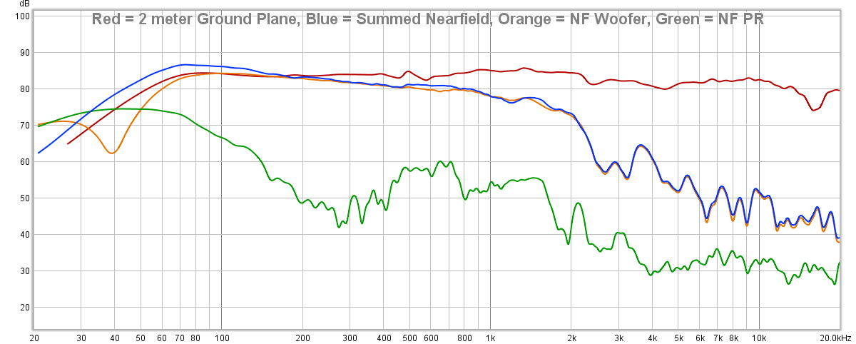
And here is the summed nearfield response above vs my ground plane (at 2 meters) measurement:
Understanding, of course, I had to "eyeball" where to overlay these in frequency, you see the presumption regarding NF responses showing a bump in the low frequencies due to the fact that it effectively ignores baffle step is indeed true: the 2 meter ground plane measurement is lower in amplitude on the low end than that of the NF components & summed response. This is to be expected and you can find the following quote on why stated in the above audioexpress link:
The farfield ground plane technique is more accurate as you can see (and as was expected). The NF summing technique gives you an idea of the low end response but isn't entirely accurate to that of a far-field response AND it requires care in the measurement, assumptions and final calculation. Honestly, I prefer the ground plane measurement method simply because it's less prone to personal error. Meaning, the more ports and woofers I have to measure individually and then add together, the greater chance for a human error to occur. Whereas a ground plane measurement is just sticking the mic a few meters in front of the speaker, running a sweep and then you're done. I would only use a nearfield method if I had no other choice due to area available or terrible weather.
Sooo, to me, the main take-home message of your tests is that the ground-plane method easily yields consistent results at low frequencies, up to 500 Hz or so. Normal indoor gated measurements will go down to 300-400 Hz (anechoic). The ground-plane measurement might therefore be a useful method to extend this low frequencies (that's what the theory always told us, but now we KNOW).
Yes. But to reiterate, it makes more sense to perform an indoors ground plane measurement instead of the speaker-on-a-stand measurement for the reasons I listed previously. At least for me.
Sooo, to me, the main take-home message of your tests is that the ground-plane method easily yields consistent results at low frequencies, up to 500 Hz or so. Normal indoor gated measurements will go down to 300-400 Hz (anechoic). The ground-plane measurement might therefore be a useful method to extend this low frequencies (that's what the theory always told us, but now we KNOW).
This leads me to the following questions and ideas:
How does the ground-plane measurement compare to near-field measurements? This will tell us more about converting from the nearfield to the farfield.
How does the ground-plane measurement compare to "microphone-in-box" measurements [1,2]? In theory, the "microphone-in-box" method yields a 2pi farfield SPL response curve. How well does this work out in practice?
Would it be possible for you to take some nearfield and mic-in-box measurements of your speaker, and compare these to the ground-plane measurements?
The DUT I have been using is one with a passive radiator so I cannot perform the MIB test. However, I had previously captured nearfield response of both the woofer and the PR.
FWIW, I am using the sd of these drivers (as they appear to be the same ones used in the Buchardt S400, with assumed differences in electro-mechanical properties; however the physial dimensions are almost certainly the exact same):
SB Acoustics SB15SFCR39-8 5x8" Paper Cone Woofer
SB Acoustics SB15NBAC30-4 5" Black Aluminum Cone Mid-bass
With the above stated, the nearfield method has a maximum frequency accuracy dictated by the size (as discussed in the above audioexpress link). The 5" woofer is limited to about 980hz and the 5x8 inch passive radiator I will limit to the 8 inch dimension and therefore is invalid above about 600hz. Just spit-balling here; not using the actual effective radius. But it's close enough.
... On with the results ...
As you may know, when capturing near-field data it's hard to get the exact same level relative to distance of mic from cone and therefore the result is usually "eyeballed" to overlay them together, by using the lowest frequencies. I have done that below. What you see below is:
Woofer Nearfield (orange)
Passive Radiator Nearfield (green)
Summed Nearfield Response of the Woofer + PR (blue)
*Note the y-axis scale is 10dB. Using 5dB is too hard to read.
And here is the summed nearfield response above vs my ground plane (at 2 meters) measurement:
Understanding, of course, I had to "eyeball" where to overlay these in frequency, you see the presumption regarding NF responses showing a bump in the low frequencies due to the fact that it effectively ignores baffle step is indeed true: the 2 meter ground plane measurement is lower in amplitude on the low end than that of the NF components & summed response. This is to be expected and you can find the following quote on why stated in the above audioexpress link:
First, Keele assumes all radiating surfaces are mounted on an infinite baffle. Under this condition, the radiation is into a “half-space” or a solid angle of 2π. However, most loudspeakers have relatively narrow baffles so they become omnidirectional at low frequencies. For this reason, the Keele approach may over estimate the low-frequency sound pressure level.
The farfield ground plane technique is more accurate as you can see (and as was expected). The NF summing technique gives you an idea of the low end response but isn't entirely accurate to that of a far-field response AND it requires care in the measurement, assumptions and final calculation. Honestly, I prefer the ground plane measurement method simply because it's less prone to personal error. Meaning, the more ports and woofers I have to measure individually and then add together, the greater chance for a human error to occur. Whereas a ground plane measurement is just sticking the mic a few meters in front of the speaker, running a sweep and then you're done. I would only use a nearfield method if I had no other choice due to area available or terrible weather.
You work really is super useful! Now we know if / how ground-plane measurements are any good. Thanks! I just payed the mirror.
Thanks a lot, sir. I really appreciate the help. I've spent quite a bit lately on various materials to test out the methods I've discussed here so I'm happy it's helpful to others and I definitely appreciate yours and others contributions to help offset my costs. You guys rock!
Wonderful thread @bikinpunk, thanks for sharing the results. I enjoyed reading about your experiments.
Wonderful thread @bikinpunk, thanks for sharing the results. I enjoyed reading about your experiments.
cool!
I need to try to capture all of this information and post it on my site just in case something ever happens with this thread.
I had someone PM me to ask if I modeled diffraction in the above NF summed response results. I think it's a worthwile question so I'll share my reply here as well:
I did not. But that was kind of the point of posting that. Most people follow the instructions provided around the internet where you simply measure each output device (woofer/port/etc), then, based on their area, calculate the contribution and attain a "combined" curve. So I did just that.
All of these factors lead me again to deciding to stick with the GP method. There's no need to model anything; no need to account for different radiating surfaces or ports and whatnot. You just measure in the farfield and you are done. But I do understand some do not have the luxury of a large area to do so.
I have been questioning nearfield summation in my mind too. I misses baffle loss for both and phase difference for summation, so summed response must be too optimistic. But I have never even tried to verify my guess.
Don't remember when Stereophile's Atkinson wrote about this same thing and said that his summed response has 2-3db extra around 100Hz, but he must continue to use same maths for consistency.
All in all, we must be very careful when looking at response curves from different sources. And still, nearfield from the port often reveals nasty midrange leakage!
Last edited:
The farfield ground plane technique is more accurate as you can see (and as was expected). The NF summing technique gives you an idea of the low end response but isn't entirely accurate to that of a far-field response AND it requires care in the measurement, assumptions and final calculation. Honestly, I prefer the ground plane measurement method simply because it's less prone to personal error. Meaning, the more ports and woofers I have to measure individually and then add together, the greater chance for a human error to occur.
Exactly what I thought. Your nearfield curves nicely illustrate the problem: the green curve (passive radiator) shows a rather wide and "flat" response. I am pretty sure this is just the crosstalk you get them the woofer. Adding the curves of the woofer measurement and the passive-radiator measurement therefore overestimates the true sum. This is not just "human error", it's rather a method that will never give accurate results due to the crosstalk.
This is why I like the mic-in-box technique. It automatically measures the summed response of the woofer + port (or passive radiator), so it does away with the crosstalk problem. It would be cool to see a comparison between mic-in-box with a ground-plane measurement, but I assume you don't want to drill a hole to insert the microphone into your speaker box. 😉
A ground-plane measurement may be easy in a typical American yard. However, my Swiss garden is a bit different -- otherwise I would have done it...
Attachments

Hi bikinpunk, nice continued work !
fwiw,
I've found indoor ground plane works much better for drivers than for speakers.
Problem is always getting the mic into the far field for the speaker, so that summation is taking place correctly.
This isn't so much of a problem for a small 2-way like you've been testing.
But as a multi-way grows in both sections and size, it often forces the GP measurement outdoors.
I've also found gating and stitching to keep from going outside, be hit or miss compared to dragging the whole shebang outdoors.
But I think my biggest growth in speaker measurements has been to toss an idea of 'accuracy', other than 'accurate mainly equals repeatable'.
Because no matter what the technique, the space, etc,... the technique is part of the measurement ...and we know measurements will vary based on such.
Which technique/space is accurate, for what purpose?
I truly love taking speaker measurements, had 5 full days of formal training last year...
but i keep learning the most when i ask "what exactly am i trying to measure and why?" 😉

I understand. And if I were presenting data to myself only then I’d probably have gone with some of the more typical methods because I know and can account for deficiencies. However, my purpose is to provide as accurate data as possible down to as low a frequency as possible because I am publishing data to my site in reviews.
Of course, the great thing about having conducted all these measurements is that I am able to pick and choose what fits for a certain application and be able to explain in the review the limitations. As opposed to going with Method A always but never quantifying the issue. Such as a 4-pi measurement conducted with a small 3-4ms window and therefore the resolution of 250-300hz steps; leaving a lot of missing data that would not able to highlight issues in the 300-1kHz region. Or if I am loaned a speaker that I really want to test but don’t have the time to wait for nice weather outside that would permit a highly accurate LF response.
Additionally, I can always take a short windowed 4-pi measurement of a larger speaker as a sanity check for HF shape before continuing with a ground plane measurement with a longer window.
Everyone is obviously free to do as they choose. But I continue to provide information here in hopes they can understand the potential pitfalls with the various methods and choose the method that makes sense for their own needs. 🙂
Last edited:
.........This is why I like the mic-in-box technique. It automatically measures the summed response of the woofer + port (or passive radiator), so it does away with the crosstalk problem. It would be cool to see a comparison between mic-in-box with a ground-plane measurement, but I assume you don't want to drill a hole to insert the microphone into your speaker box. 😉
...
Matthias, here are some comparisons of merging technique vs MiB (always think on Man in Black when i write 🙂 ):
Measured woofer and PR nearfield and merged:

Microphone inside the box:
-Microphone-inside-technique-measurements.png")
Source: Puri Bliss - BeWg | HiFiCompass - всё для акустических систем и не только
Last edited:
hardisj said:I had someone PM me to ask if I modeled diffraction in the above NF summed response results. I think it's a worthwile question so I'll share my reply here as well:
I did not.

Ughhhh.... Ok. Curiosity got the best of me. But I swear, I AM DONE after this!....
Now, let me state: I have never used VituixCAD for this purpose but I *think* I did this correctly...
I opened the Diffraction Tool.
I loaded my NF curve in the Half space response section
I checked "full space"
I modeled the enclosure with the woofer in the appropriate place on the baffle.
I modeled the microphone about where the tweeter axis is.
I set the mic distance to 2 meters.
I saved this response.
I repeated the same process for the passive radiator (using a rectangular driver since it's an oval).
I then used VituixCAD's Calculator Tool to sum the those (2) curves. What you see below is a comparison of the original 2 meter far field in Red vs the different NF sums. In blue is the summed woofer & PR response *WITHOUT* diffraction modeled. In black is the summed woofer & PR *WITH* diffraction modeled.
As I posted previously, the simple NF sum of the woofer + passive radiator (blue) shows a boost on the low end that was expected. HOWEVER, if you apply the diffraction effect to each of the components and then sum them (black) you get a combined response that follows the 2 meter GP measurement (red) quite well. Close enough, in fact, that I would feel comfortable using this method in future tests if I don't have the ability to physically measure outdoors to get the LF extension in response I need. It isn't perfect but I think it shows the necessity for modeling the diffraction effects for those of you who are dealing with how best to accurately gather data for your reviews or your own designs.
Okay. That's it! I'm done!!! I have to quit obsessing over this topic. Thanks for joining me in this journey. But I've gotta bail. I'm out of money and I'm out of sanity!

😀 😀
Thank you again! In previous post we can also see what source pathlength difference and missing phase info means for summation - above 400Hz the wiggles in GP response don't happen in summed responses.
The port sound in basically in opposite phase to driver signal, but in the port tube it gets reversed at resonance freq. but phase match gets weaker when freq goes up. I am poor at maths, but sims and models focuse on what happens at the port resonant frequency.
Bass Reflex Loudspeakers
Engineering Acoustics/Bass Reflex Enclosure Design - Wikibooks, open books for an open world
The port(s) are on front, back or bottom panel of the box..
Notice also how blue summed curve goes low in spl above 200Hz...
Last edited:
Ok... Nearfield measurements can be difficult to get right; you'll need a sophisticated diffraction model (with all it's uncertainties), and crosstalk between woofer and port/passive-radiator is still an issue that tends to result in an overestimated bass SPL.
Your point is very clear: go for ground plane measurements and you'll know you get a good result without messing with the data.
Your point is very clear: go for ground plane measurements and you'll know you get a good result without messing with the data.
Excellent thread. Thanks for sharing your journey and thought process.
Measurements can be fun and also frustrating!
Your final take away observations mirror my own for the most part. GP is the easiest method in most cases, especially for LF <300Hz, but poses real challenges due to weather, wind, back ground noise and the available surface for repeatable HF measurements. It would be great to be able to take a single measurement for LF-HF, but most of us don't have repeated access to gymnasium's unfortunately.
Did you happen to try the plywood in the driveway? I'm curious if it would be different than when placed in the yard. It shouldn't be much different but something tells me it would be. Perhaps you did this already and I missed it. This was the one result that was surprising to me. I would not have guessed the plywood sheets would show so much deviation from the driveway measurements.
Hey Josh. No, I haven’t tested plywood directly on the driveway. I did not plan on testing that. However, I was planning on testing a raised platform. The reason why is because if the result doesn’t change (or change much), then I can build a motorized turntable underneath the platform without affecting the results. Otherwise any turntable I build will raise the speaker up off the ground and therefore alter the results in a baffle step fashion. My thinking was that if I build a platform for both the microphone and a speaker may be the result would not change much and even if it did I could use a calibration file since I know what the flat floor response should be.
Like Josh, I find the deviation of the plywood measurements from the driveway measurements interesting.Hey Josh. No, I haven’t tested plywood directly on the driveway.
Either the sound absorption coefficient of the ground plane measuring surface accounts for the difference, or something else in the test set up does. I'm still curious as to the cause of the difference.
Art
I have started back to work again. So I don't have the extra time not sitting in traffic on my way to work I did the past few weeks. Not sure I'll make plywood in the driveway testing a priority at this point as I have other tasks in my measurement agenda that take precedence. But if I do, I will share the data as I have all the previous rounds of tests.
I tried out the Keele NF method to measure my recent 2-way reflex box. It worked quite well once I figured out how to scale vent response with main woofer response in NF.
I use the Audioexpress article linked in post 111 above (although I found it on my own out of necessity).
I decided to match far and near field based on 150Hz response.
This gave a -3dB value and overall sensitivity that matches the predicted bass reflex calculator which predicted 45Hz tuning (which also matches impedance sweep saddle between the two reflex peaks).
Overall a nice result that tells me a lot more than the far field curve that always seems to drop below 100Hz.
Attachments

- Home
- Loudspeakers
- Multi-Way
- Measuring Response: How close is "close enough" to anechoic?