To get vertical and horizontal data, that's merging about 60 files down to about 30.
VituixCAD does this. It's just a case of naming the files according to a convention (include angle and vertical/horizontal) and than specifying the range over which you want to blend the NF/FF.
VituixCAD does this. It's just a case of naming the files according to a convention (include angle and vertical/horizontal) and than specifying the range over which you want to blend the NF/FF.
I didn't realize. I thought it was one at a time. I'll look in to this.
")
Edit: Yep, sure enough. But, I think I'll stick with my own script because I just tell it what folder to look in and it populates all the data automatically for me. But it's good to know virtuixCAD does this in case I need a fall-back for some reason. Thanks!
Last edited:
bikinipunk,
Really good work. Thanks for taking the time and effort to do this.
No problem. Figured I might as well share. If nothing else, it'll be a way for me to remember what I did when I forget in a week.
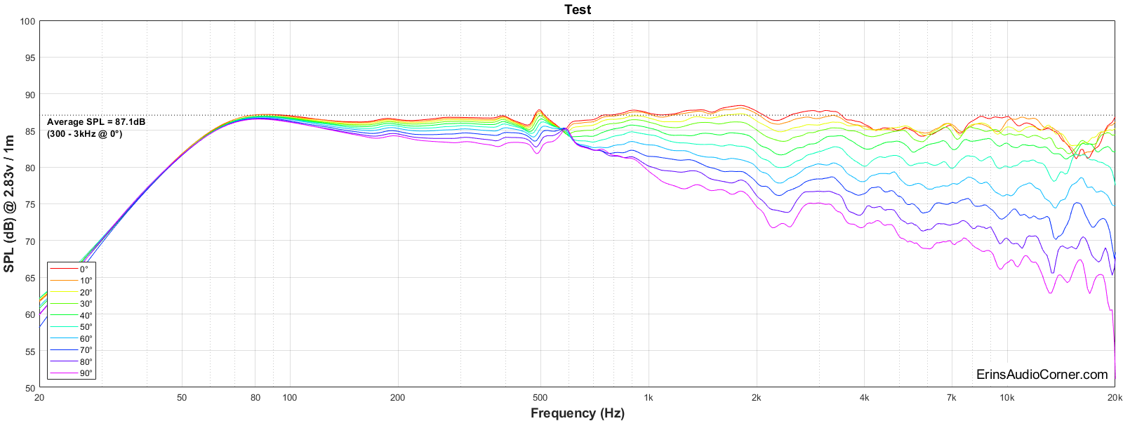
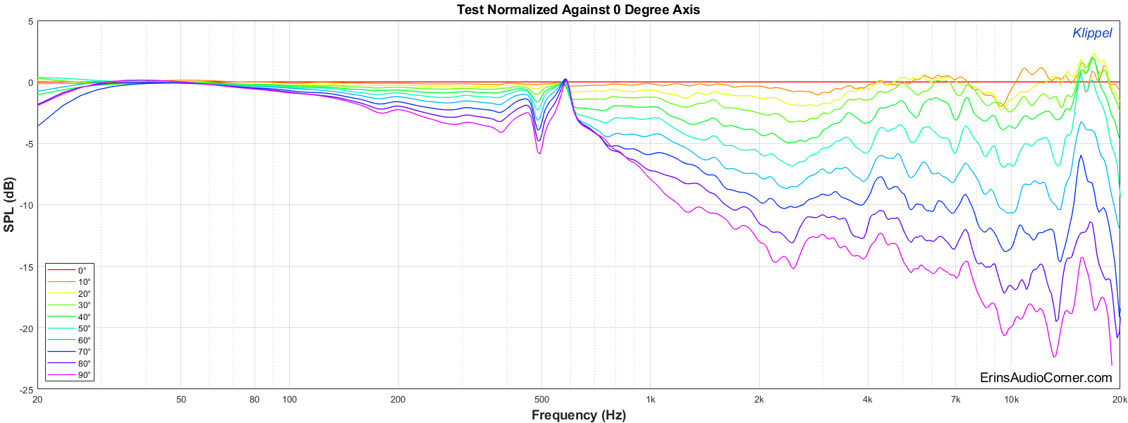
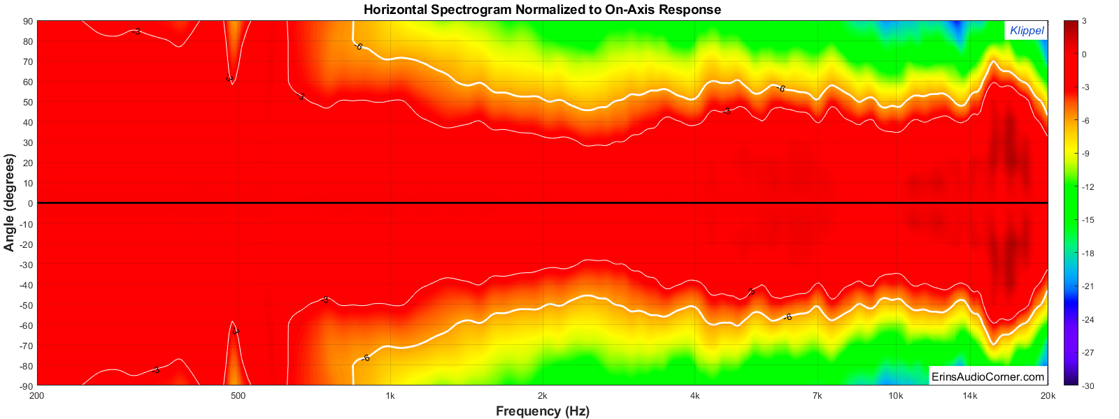
Okay. I used my script to run the horizontal polars. Looks pretty darn good.
I'll have to clean up the script but I am happy with how it works so far. I have it set up to where I point Matlab at the directory and it prompts me for the stitch frequency, I tell it where, then it dumps out the following plots. I'll have to add info for verticals. Then there's the impedance/phase, IMD, max SPL, and other tests. But I think I finally have decided on how I am going to test and the scripts will help me automate the presentation of the data so I can focus on the analysis aspect.
I'll have to clean up the script but I am happy with how it works so far. I have it set up to where I point Matlab at the directory and it prompts me for the stitch frequency, I tell it where, then it dumps out the following plots. I'll have to add info for verticals. Then there's the impedance/phase, IMD, max SPL, and other tests. But I think I finally have decided on how I am going to test and the scripts will help me automate the presentation of the data so I can focus on the analysis aspect.
Last edited:
Great Info
I just stumbled across this thread. I found this information very helpful and I thank you for your efforts. Much appreciated.
Donated!
......found this information useful enough..... and you don't mind contributing a little bit to the cause I would definitely appreciate it.
https://www.erinsaudiocorner.com/contribute/
I just stumbled across this thread. I found this information very helpful and I thank you for your efforts. Much appreciated.
Donated!
I just stumbled across this thread. I found this information very helpful and I thank you for your efforts. Much appreciated.
Donated!
Wow! Thanks, man! I really appreciate that.
I am going to try to recap everything I have learned thus far.
As we know by now, there are many ways to measure a speaker's response. All with their own pros and cons. My efforts reveal that a 2-pi ground plane measurement can give the same accuracy as a 4-pi "speaker in the sky" measurement. And it's a lot easier. So I will measure in the garage for mid/high frequency accuracy and outdoors as needed for low frequency stitching. As for rotating the speaker, I built a turntable using a NEMA-23 motor and a USB stepper motor controller but the platform height is currently of concern. I'll work through this. If all else fails I'll manually rotate the speaker. It's easier to do this than it is to wait for the perfect weather and rig up a heavy speaker high in the sky. That's the method I choose. If others choose to use the 4-pi speaker on a stand method that's fine. Again, both are fine methods.
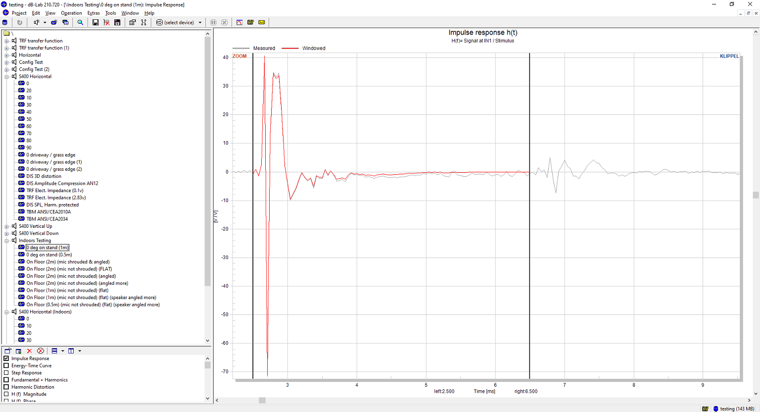
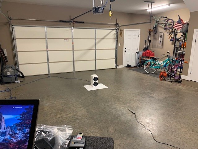
However, it is worth noting that in my garage using the Ground Plane method I can place my DUT and mic in the center of the garage, clear items out from the sidewalls and get about 11ms free of reflection window as you can see at the bottom of this post. This is significantly better than if I were to place the speaker on a stand in my garage and measure; at which point I would get about 4ms of reflection-free time (due to the floor and ceiling in my 10 foot tall garage space). That's the difference in having a data point approximately every 90hz (11ms) vs every 250hz (4ms). And for no other reason encourages one to at least consider a proper ground plane measurement in lieu of the standard 4-pi method.
The thing to note about ground plane measurements are they need to be in an area that is obviously far, far away from the nearest boundary (wall, vehicle, etc) if you want low frequency accuracy (same as any other method). And it also needs to be in an area that has a large reflective surface. You don't need a mirror (as I have shown). But concrete is necessary and grass will not cut it (ha! no pun intended). If you are looking to perform LF response only measurements and all you have is an open field to measure in, then you can probably get away with 300hz as the maximum range (my data shows 400hz in my backyard with very low cut grass). I would not trust the data higher than that, however. Plywood is NOT a good substitution.
Any measurements performed outdoors need to be performed when there is practically no wind. A little wind is tolerable but more than a couple mph and the HF data is corrupted and considerably moreso if the wind is higher (as I have shown).
And, finally, these are all just my results. I encourage you to do your own tests if you have the desire to measure your own loudspeakers. Let my results guide you but understand that different surface areas and conditions will effect the results and you need to quantify those differences before you go willy-nilly with measurements. I have seen a lot of measurements since I started this quest that make me question the accuracy and reliability because of the knowledge I have gained from my own testing of the different methods. But, such is life. As long as you understand what you're doing and you can back it up with data then you can better provide analysis.
Hopefully some of you gained some useful information from this. I know it has been enlightening to myself as well as many others in the other forums.
- Erin
Ground Plane Impulse Reflection-Free Window ( ~ 11ms wide; 90hz data point intervals)
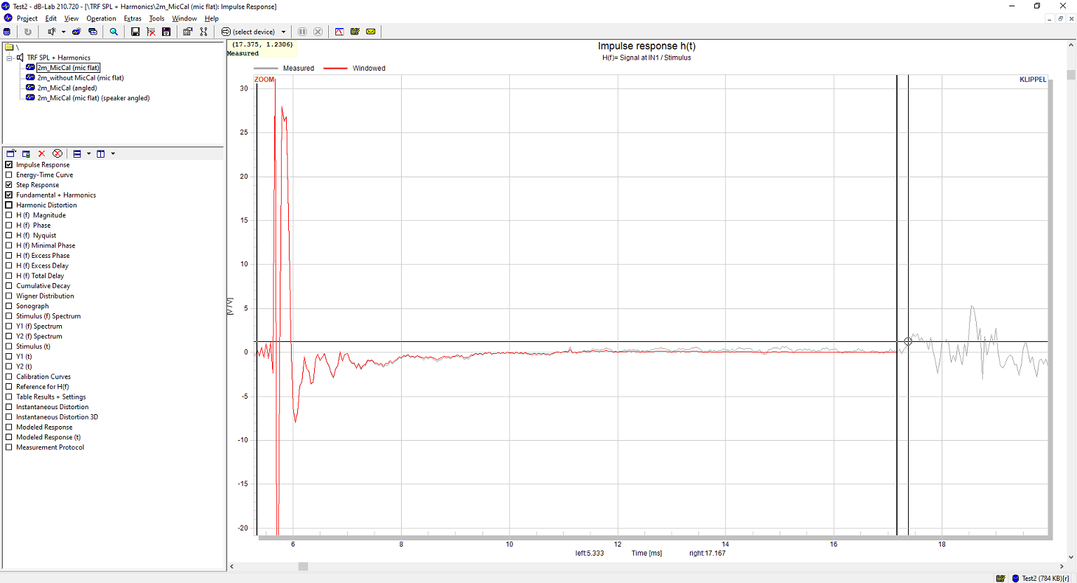
Stand Mounted Impulse Reflection-Free Window ( ~ 4ms wide; 250hz data point intervals)
As we know by now, there are many ways to measure a speaker's response. All with their own pros and cons. My efforts reveal that a 2-pi ground plane measurement can give the same accuracy as a 4-pi "speaker in the sky" measurement. And it's a lot easier. So I will measure in the garage for mid/high frequency accuracy and outdoors as needed for low frequency stitching. As for rotating the speaker, I built a turntable using a NEMA-23 motor and a USB stepper motor controller but the platform height is currently of concern. I'll work through this. If all else fails I'll manually rotate the speaker. It's easier to do this than it is to wait for the perfect weather and rig up a heavy speaker high in the sky. That's the method I choose. If others choose to use the 4-pi speaker on a stand method that's fine. Again, both are fine methods.
However, it is worth noting that in my garage using the Ground Plane method I can place my DUT and mic in the center of the garage, clear items out from the sidewalls and get about 11ms free of reflection window as you can see at the bottom of this post. This is significantly better than if I were to place the speaker on a stand in my garage and measure; at which point I would get about 4ms of reflection-free time (due to the floor and ceiling in my 10 foot tall garage space). That's the difference in having a data point approximately every 90hz (11ms) vs every 250hz (4ms). And for no other reason encourages one to at least consider a proper ground plane measurement in lieu of the standard 4-pi method.
The thing to note about ground plane measurements are they need to be in an area that is obviously far, far away from the nearest boundary (wall, vehicle, etc) if you want low frequency accuracy (same as any other method). And it also needs to be in an area that has a large reflective surface. You don't need a mirror (as I have shown). But concrete is necessary and grass will not cut it (ha! no pun intended). If you are looking to perform LF response only measurements and all you have is an open field to measure in, then you can probably get away with 300hz as the maximum range (my data shows 400hz in my backyard with very low cut grass). I would not trust the data higher than that, however. Plywood is NOT a good substitution.
Any measurements performed outdoors need to be performed when there is practically no wind. A little wind is tolerable but more than a couple mph and the HF data is corrupted and considerably moreso if the wind is higher (as I have shown).
And, finally, these are all just my results. I encourage you to do your own tests if you have the desire to measure your own loudspeakers. Let my results guide you but understand that different surface areas and conditions will effect the results and you need to quantify those differences before you go willy-nilly with measurements. I have seen a lot of measurements since I started this quest that make me question the accuracy and reliability because of the knowledge I have gained from my own testing of the different methods. But, such is life. As long as you understand what you're doing and you can back it up with data then you can better provide analysis.
Hopefully some of you gained some useful information from this. I know it has been enlightening to myself as well as many others in the other forums.
- Erin
Ground Plane Impulse Reflection-Free Window ( ~ 11ms wide; 90hz data point intervals)
Stand Mounted Impulse Reflection-Free Window ( ~ 4ms wide; 250hz data point intervals)
Last edited:
What was the stitch frequency? REW's merge function does a very good job of phase matching and could be used as a comparison but it wouldn't help the automation like the script does.Okay. I used my script to run the horizontal polars. Looks pretty darn good.
What was the stitch frequency? REW's merge function does a very good job of phase matching and could be used as a comparison but it wouldn't help the automation like the script does.
Approximately 800hz. And even knowing this you can't tell in the data, or at least I can't. One might look at the 90 degree plot and think "oh, it shows up there" but that's actually how it looks even in the "full range" ground plane measurements I posted previously (where I had used the shroud around the mic and it corrupted the data above 3kHz):
https://www.audiosciencereview.com/forum/index.php?attachments/crap-s400-png.62064/
As long as I choose a point where the resolution is high enough in the windowed measurement (mid/high frequency) then it will be easier. In this case my data had resolution down to about 200hz. If I were stitching a 3ms window to the LF window it would have been more obvious.
I plan on modifying my script to blend within an octave instead of hard splice, though. Should be pretty simple and help clean up any conditions where my data points don’t quite line up as well as I would like.
Last edited:
Here's some information for those of you who may want to conduct their own measurements with the ground plane method.
I've mentioned it numerous times but in case someone didn't catch it or doesn't already know: when you measure a speaker in the ground plane you need to tilt the speaker some angle in order to line up the speaker with the microphone axis. This is covered in various places online and discussed in D'Appolito's "Testing Loudspeakers" book. It's a pretty simple tangent equation but there are calculators online to make this easy for you. Here's one: HiFi Loudspeaker Design
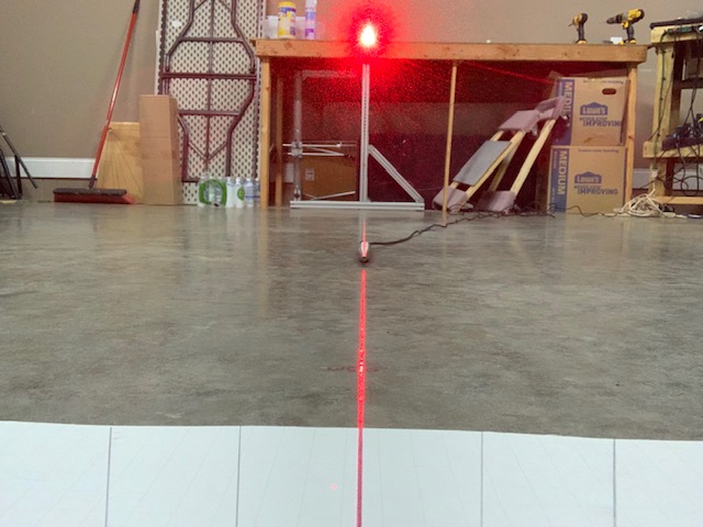
You enter the mic distance from the speaker and the distance from the ground to the tweeter (or other reference axis; say, midpoint between tweeter and midrange). This site recommended using your phone in "selfie" mode to make sure the microphone shows up in the center of the image. I do this from time to time to sanity check the calculations. You can see my 4th image below displaying this method.
Now, what I've read before is it is OK if you are off a little bit. But I thought it would be helpful for me to show just how much the tilt angle matters so in this example I am using the same Buchardt S400 in my garage.
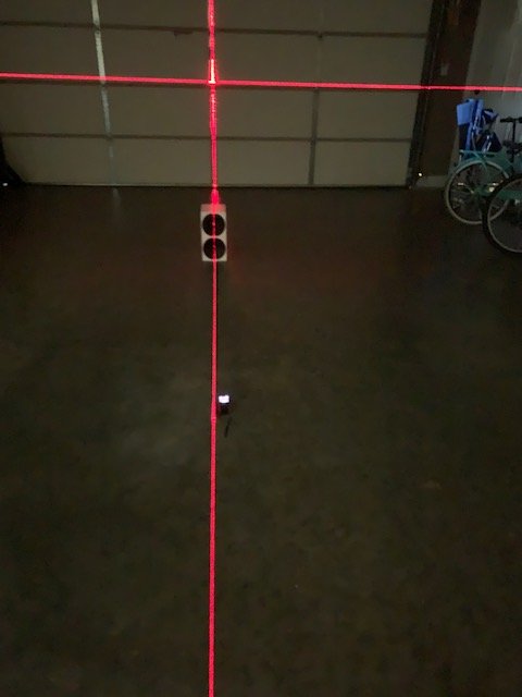
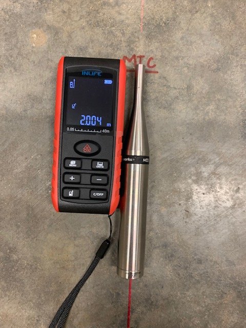
First I used a laser level to draw a line on my garage floor to make sure the microphone was on-axis with the speaker. I also used a distance finder to make sure the distance was at 2 meters.
**
Side note, if you are interested, these are the two items I use and am quite happy with them. About half the price of the hardware store versions. If you plan on doing GP measurements in your garage, these will make your life so much easier and improve accuracy of your aiming/setup. I recommend you buy them. If not these, something along these lines. The links below are made with my Amazon affiliate link so if you do purchase them I'll get 2%... hey, every little bit helps.
Laser Level
Laser Distance Finder (bonus: this thing has an angle detector which is perfect for determining speaker tilt angle)
**
Anyway, here's some photos:
Selfie Photo to make sure the microphone is at the center of the image; meaning it is lined up with the tweeter axis.
Now, keep in mind the Buchardt S400 has a 2 degree tilt on both the baffle and the rear. Literally, it looks like a parallelogram instead of a typical box enclosure.
1) The first test was ran with the speaker flat. (Red)
2) I then used the site above, entering the distance as 2 meters and the tweeter height as 4.5 inches (~ 10cm). I got a tilt angle of 2.9 degrees. I thought, hey, let's overcompensate here and add the 2 degree tilt from the enclosure itself, so I came to 4.9 degrees total. (Blue)
3) I then remeasured at 2.9 degrees (no factory tilt accounted for). (Green)
Here is the result.
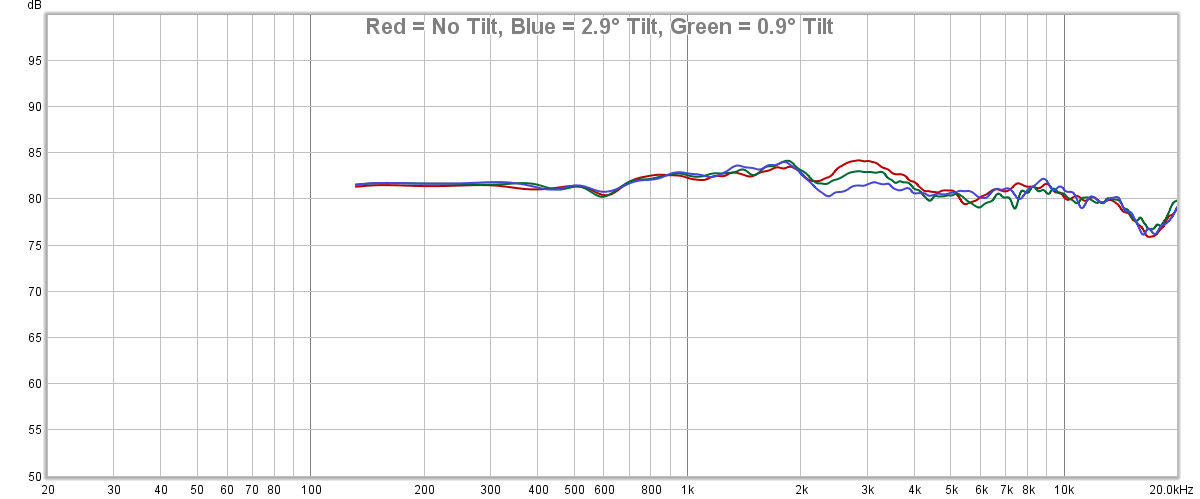
You can see there is indeed a notable difference in the 2-4kHz region between the 3 measurements (and a smaller difference from 5-8kHz). I think this can be telling of the best axis to listen on but that's for a different time. For now, the point is: the tilt angle even within 5 degrees has approximately 3.0dB difference at about 3kHz. And the 0.9° vs 2.9° difference at 3kHz is approximately 1.5dB.
What does this mean? I think it means that care should be taken to ensure the intended axis of measure (the tweeter, between tweeter/mid, etc) is used as the reference plane and the speaker tilted as necessary to make this so.
Obviously, YMMV (your mileage may vary) depending on the speaker, distance, etc. But I would urge you to take care to make sure the tilt angle is correct before you continue with the measurement process.
- Erin
I've mentioned it numerous times but in case someone didn't catch it or doesn't already know: when you measure a speaker in the ground plane you need to tilt the speaker some angle in order to line up the speaker with the microphone axis. This is covered in various places online and discussed in D'Appolito's "Testing Loudspeakers" book. It's a pretty simple tangent equation but there are calculators online to make this easy for you. Here's one: HiFi Loudspeaker Design
You enter the mic distance from the speaker and the distance from the ground to the tweeter (or other reference axis; say, midpoint between tweeter and midrange). This site recommended using your phone in "selfie" mode to make sure the microphone shows up in the center of the image. I do this from time to time to sanity check the calculations. You can see my 4th image below displaying this method.
Now, what I've read before is it is OK if you are off a little bit. But I thought it would be helpful for me to show just how much the tilt angle matters so in this example I am using the same Buchardt S400 in my garage.
First I used a laser level to draw a line on my garage floor to make sure the microphone was on-axis with the speaker. I also used a distance finder to make sure the distance was at 2 meters.
**
Side note, if you are interested, these are the two items I use and am quite happy with them. About half the price of the hardware store versions. If you plan on doing GP measurements in your garage, these will make your life so much easier and improve accuracy of your aiming/setup. I recommend you buy them. If not these, something along these lines. The links below are made with my Amazon affiliate link so if you do purchase them I'll get 2%... hey, every little bit helps.
Laser Level
Laser Distance Finder (bonus: this thing has an angle detector which is perfect for determining speaker tilt angle)
**
Anyway, here's some photos:
Selfie Photo to make sure the microphone is at the center of the image; meaning it is lined up with the tweeter axis.
Now, keep in mind the Buchardt S400 has a 2 degree tilt on both the baffle and the rear. Literally, it looks like a parallelogram instead of a typical box enclosure.
1) The first test was ran with the speaker flat. (Red)
2) I then used the site above, entering the distance as 2 meters and the tweeter height as 4.5 inches (~ 10cm). I got a tilt angle of 2.9 degrees. I thought, hey, let's overcompensate here and add the 2 degree tilt from the enclosure itself, so I came to 4.9 degrees total. (Blue)
3) I then remeasured at 2.9 degrees (no factory tilt accounted for). (Green)
Here is the result.
You can see there is indeed a notable difference in the 2-4kHz region between the 3 measurements (and a smaller difference from 5-8kHz). I think this can be telling of the best axis to listen on but that's for a different time. For now, the point is: the tilt angle even within 5 degrees has approximately 3.0dB difference at about 3kHz. And the 0.9° vs 2.9° difference at 3kHz is approximately 1.5dB.
What does this mean? I think it means that care should be taken to ensure the intended axis of measure (the tweeter, between tweeter/mid, etc) is used as the reference plane and the speaker tilted as necessary to make this so.
Obviously, YMMV (your mileage may vary) depending on the speaker, distance, etc. But I would urge you to take care to make sure the tilt angle is correct before you continue with the measurement process.
- Erin
Last edited:
^ too late to edit but I realized my explanation of the angles was a bit confusing so hopefully this makes sense:
Now, keep in mind the Buchardt S400 has a 2 degree tilt on both the baffle and the rear. Literally, it looks like a parallelogram instead of a typical box enclosure.
1) The first test was ran with the speaker bottom flat on the floor; not tilted forward. (Red)
2) I then used the site above, entering the distance as 2 meters and the tweeter height as 4.5 inches (~ 10cm). I got a suggested tilt angle of 2.90°. I thought, hey, let's overcompensate here and also add the 2° tilt from the enclosure itself, so I came to 4.90° total. Therefore, the actual angle of the baffle perpendicular to the floor was now 2.90° (4.90°-2.00°). (Blue)
3) I then remeasured at 2.90° (no factory tilt accounted for) and the actual angle of baffle perpendicular to floor was 0.90° (2.90°-2.00°). (Green)
A tower speaker shoud be laid on it's side for the best on-axis measurement. Then measure it standing too, and you can get a compensating curve/custom calibration file! With the speaker standing, you can rotate it to take horizontal off-axis measurements.
How does this sound?
How does this sound?
Shameless plug, but if any of you guys have a few extra bucks and found this information useful enough to do so and you don't mind helping me out, I spent about $30 on the pavers & $20 on the mirror and have no real use for them now that I've shown they don't help but unfortunately cannot return them. So if you don't mind contributing a little bit to the cause I would definitely appreciate it. It's not that I wouldn't have done all this anyway. It would just be appreciated and help me offset my costs a little bit if you deem it worthwhile.
https://www.erinsaudiocorner.com/contribute/
You work really is super useful! Now we know if / how ground-plane measurements are any good. Thanks! I just payed the mirror.
Sooo, to me, the main take-home message of your tests is that the ground-plane method easily yields consistent results at low frequencies, up to 500 Hz or so. Normal indoor gated measurements will go down to 300-400 Hz (anechoic). The ground-plane measurement might therefore be a useful method to extend this low frequencies (that's what the theory always told us, but now we KNOW).
This leads me to the following questions and ideas:
Would it be possible for you to take some nearfield and mic-in-box measurements of your speaker, and compare these to the ground-plane measurements?
1: R H Small. Simplified loudspeaker measurements at low frequencies. Journal
of Audio Engineering Society (JAES), 20:28–33, 1972. (I have a PDF copy of the paper if you need it)
2: Measuring Loudspeaker Low-Frequency Response | audioXpress (scroll down about half-way)
This leads me to the following questions and ideas:
- How does the ground-plane measurement compare to near-field measurements? This will tell us more about converting from the nearfield to the farfield.
- How does the ground-plane measurement compare to "microphone-in-box" measurements [1,2]? In theory, the "microphone-in-box" method yields a 2pi farfield SPL response curve. How well does this work out in practice?
Would it be possible for you to take some nearfield and mic-in-box measurements of your speaker, and compare these to the ground-plane measurements?
1: R H Small. Simplified loudspeaker measurements at low frequencies. Journal
of Audio Engineering Society (JAES), 20:28–33, 1972. (I have a PDF copy of the paper if you need it)
2: Measuring Loudspeaker Low-Frequency Response | audioXpress (scroll down about half-way)
Speaker-in-box is by the way used at Genelec factory for standard QC for each minimonitor unit! Been there, seeen that.
In-box might be difficult, seal must be perfect and in practice you must make special boxes for each type. OK for QC but problematic for diy unique speakers.
I really like the idea of merged GP/quasi-anechoic gated. This will need more testing to find out how off-axis responses match.
Another challenge is 90-180deg (backside) measurements. From ASR we have learned how informative they can be eq. to find out the 5-600Hz wiggle of Buchardt S400.
In-box might be difficult, seal must be perfect and in practice you must make special boxes for each type. OK for QC but problematic for diy unique speakers.
That may be true for sealed enclosures. Not so for bass reflex etc, where the mic-in-box elegantly avoids the issues of merging the nearfield SPL respose curves of the woofer and the port, with all the issues of crosstalk between the two.
- Home
- Loudspeakers
- Multi-Way
- Measuring Response: How close is "close enough" to anechoic?