hi trevmar - I'd like to see a Karlsonator for 15" tuned somewhere around 40Hz. The 12" Karlsonator (original by Greg B) is tuned to 37Hz, so if scaled might be tuned too low for punch (?)
Have you thought of tweaking the length of the transmission-line/horn by reducing the height of the Karlsonator cabinet a little? If you want to move from 40Hz to 37Hz that would be a minor design tweak. I would also suspect the amount of padding would affect it that much, depending how you place the padding in the transmission line.
It also occurred to me that there seems to be no need for the exponential radiation cutout to partly obscure the speaker when a full-range driver is in use. Again, I would try to tweak the height of the enclosure a little to fully expose the speaker. Maybe some 'felt' on the insides of the exponential slot would reduce the mid-range resonances between the slot and the front of the driver. Has anybody tried this?
No design is magic, and small tweaks are going on all the time as folk change drivers when they scale the full-size design. But I haven't any experience with this particular speaker enclosure topology...
Wait - I see what you are asking -- how to get the 15" speaker to fit on the baffle board, which isn't quite that wide at a 1.0 scale. And when you scale the Karsonator up to produce a bigger baffle board you will get a lower frequency than 37Hz. Did I get it right this time?
OK, here are my thoughts. First, the driver characteristics do make a difference. Horns and transmission lines tend to like a high speaker Qts ( >0.5 ) but that is not an inviolate rule. Best way to see exactly what would happen would be to use modelling software such as Martin J King's, which should be able to deal with the design up until the exponentially dissipative end termination. You will need to approximate the length of this final piece of 'tube' as the frequencies are leaked (radiated) progressively by the exponential taper. One approximation attractive to me is to assume that the length of that final piece of 'tube'/horn ends about halfway along the exponential curve.
But you are correct, to increase the size of the speaker mounting baffle you would have to expand the cabinet size which will increase the length of the transmission-line/horn. That will lower the resonant frequency, and you would need to reduce the length of the line, possibly by reducing the height of the case (and of the internal 'tubing' baffles, of course). That's just a suggestion, I haven't tried it. You would be best to model using Martin King's software...
maybe Leonard - Audio's T-line simulator could do the work
Leonard Audio | Audio Engineering Resources
Greg B came with the "Karlsonator" scheme a few years ago - if directly scaled in all three directions, its bulk would be about 10 cubic feet and possibly tuned too low for some 15" . Some Russian came up with very similar to Greg's idea for a weak motor fullrange speaker.
t-line and tapped pipes seem like good alternatives to reflex
I have an Eminence Beta10cx in one of my Karlsoator 12s - don't like its midrange - maybe Eminence's lowpass filter of 2mH/10uF is too much (?) - a 12LTA does better. I may put in a custom Eminence 12" cast frame coax with qts around 0.5
Beta10cx - this did play loud and low with seemingly low cone excursion - maybe the low cone excursion is an illusion? I know the original Karlson K15 plays with less excursion than a reflex equal to its rear chamber volume and same fb.
Last edited:
Not sure why I would be offended - no worries. If you would like me to run a sim in Akabak - like I told Freddi, I will be without Akabak for some time.
Thank you!
Please excuse me if this is a stupid query, but I don't understand one "step" in these builds. FYI - I've got two TC9FD drivers, so I want to build the single driver .40x Karlsonator, using Muddjester's cut and fold plan (linked in post #1).
I printed the 6 pages on standard 8.5" x 11" paper in my printer, so now I want to transfer the patterns onto the fcb... sized up to proper dimensions for cutting. How is this being done?
I thought that I would take the 6 pages to a print shop, to get them copied onto larger scale paper. However, my quick review of some pages seems to indicate that the scales differ between pages... so I'm not sure what instructions I would give to the print shop.
I know that there are various plans (.53, double drivers, cornu) for these builds & xrk's other projects, so I feel that it is not just Muddjester's plans. I think that I'm missing something (basic?) here, but searching through a bunch of posts hasn't helped.
Thanks, Ron
Please excuse me if this is a stupid query, but I don't understand one "step" in these builds. FYI - I've got two TC9FD drivers, so I want to build the single driver .40x Karlsonator, using Muddjester's cut and fold plan (linked in post #1).
I printed the 6 pages on standard 8.5" x 11" paper in my printer, so now I want to transfer the patterns onto the fcb... sized up to proper dimensions for cutting. How is this being done?
I thought that I would take the 6 pages to a print shop, to get them copied onto larger scale paper. However, my quick review of some pages seems to indicate that the scales differ between pages... so I'm not sure what instructions I would give to the print shop.
I know that there are various plans (.53, double drivers, cornu) for these builds & xrk's other projects, so I feel that it is not just Muddjester's plans. I think that I'm missing something (basic?) here, but searching through a bunch of posts hasn't helped.
Thanks, Ron
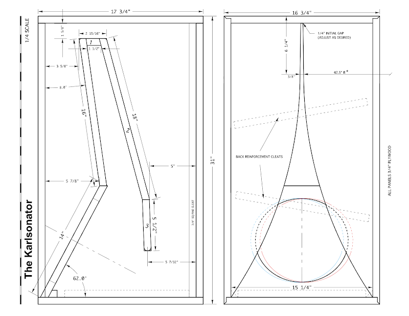
Don't get too hung up on exact dimensions. Use the main side plan view that shows the bends and kinks, and folds. Take the main dimensions and transcribe onto your workpiece with a ruler. Start at bottom left corner as reference coordinate. For example, go up 4.84in and to the right 2.48 in, round off to nearest 1/10in. or 4.8in and 2.5in. That is point of setback of angled driver panel. Follow that on up to next point. There are only 5 such major points and the four corners of the box. You could define the entire plan with:
(2.5,4.8), (11.3, 1.6), (11.3, 2,75), (4.6, 4.4), (4.6, 2.2) and box is 6.8 deep x 12.2 tall. That fully defines the 0.4x Karlsonator with width of 6.0in.
Anyone with a ruler can make that now.
Hope that helps.
Please excuse me if this is a stupid query, but I don't understand one "step" in these builds. FYI - I've got two TC9FD drivers, so I want to build the single driver .40x Karlsonator, using Muddjester's cut and fold plan (linked in post #1).
I printed the 6 pages on standard 8.5" x 11" paper in my printer, so now I want to transfer the patterns onto the fcb... sized up to proper dimensions for cutting. How is this being done?
I thought that I would take the 6 pages to a print shop, to get them copied onto larger scale paper. However, my quick review of some pages seems to indicate that the scales differ between pages... so I'm not sure what instructions I would give to the print shop.
I know that there are various plans (.53, double drivers, cornu) for these builds & xrk's other projects, so I feel that it is not just Muddjester's plans. I think that I'm missing something (basic?) here, but searching through a bunch of posts hasn't helped.
Thanks, Ron
I'm not sure what is causing your confusion. Is it just that you want to scale the drawing and all the sheets aren't scaled the same? Most people lay it out by hand with a ruler, which is why I put 1/32 increments on it.
You're right that the scaling is different on different sheets. That's to fill the sheets for legibility. Sheets 2, 3, 4 (the cut details) are scaled 1:4 (so blow it up by 4x). Sheet 5 (the side view) is 1:2. And sheet 6 (the Aperature shape) is 1:1.
"transcribe onto your workpiece with a ruler"
"Most people lay it out by hand with a ruler"
ok. Thank you, guys. And thank you for the additional clarification about how the pages were scaled, Muddjester.
As mentioned, I didn't quite get that. I was under the impression that people were basically placing the templates directly onto the fcb somehow, and I didn't get how. I was wrong again!
ok. Hope to get Karlsonators done this week coming up (vacation), but first priority is to finish building CD storage units.
Thanks, Ron
"transcribe onto your workpiece with a ruler"
"Most people lay it out by hand with a ruler"
ok. Thank you, guys. And thank you for the additional clarification about how the pages were scaled, Muddjester.
As mentioned, I didn't quite get that. I was under the impression that people were basically placing the templates directly onto the fcb somehow, and I didn't get how. I was wrong again!
ok. Hope to get Karlsonators done this week coming up (vacation), but first priority is to finish building CD storage units.
Thanks, Ron
I understand were you're coming from. At first I was trying to think of a way to transfer it, to avoid the tedious and inaccurate measuring and marking by hand. I didn't want to create an extra interface by gluing a paper on because that felt like asking for a leaky cabinet, so short of transfer through tracing carbon paper or something (which I don't have on hand and didn't want to specifically order it for this build), I couldn't think of anything. I ended up cutting most of the foam core on my table saw, then I had to measure the scoring lines and layout the side wall by hand. What it comes down to is do whatever works best for you.
Hi xrk971,
I just finished a 0.4 scale mini karlsonator with 3FE25. Just to see how it sounds, couldn't even wait for the glue to fully dry, I hooked it up and have to say it sounds amazing. Its much better than the current desktop system I have, even better than many of the mid range commercial systems. I will work on getting the other speaker of the pair completed. Thanks for your amazing design.
One thing I did do was instead of using two layers of foam core I 3d printed the speaker mount part. This is making me wonder if its worth while 3d printing the whole thing. It will come out cheaper considering a sheet of A1 foam core cost around £4.
What's the minimum dimensions I can get away with using faital pro 3FE25 drivers? I am using it for near field in a small room so loudness is not an issue, just wanted to maintain the frequency response.

Hi xrk971,
I just finished a 0.4 scale mini karlsonator with 3FE25. Just to see how it sounds, couldn't even wait for the glue to fully dry, I hooked it up and have to say it sounds amazing. Its much better than the current desktop system I have, even better than many of the mid range commercial systems. I will work on getting the other speaker of the pair completed. Thanks for your amazing design.
One thing I did do was instead of using two layers of foam core I 3d printed the speaker mount part. This is making me wonder if its worth while 3d printing the whole thing. It will come out cheaper considering a sheet of A1 foam core cost around £4.
What's the minimum dimensions I can get away with using faital pro 3FE25 drivers? I am using it for near field in a small room so loudness is not an issue, just wanted to maintain the frequency response.
Congrats! 0.4x is about as small as you can make it. Smaller and bass won't be deep and balance may not be good. 3D printing is way to go.
"Karlsonator" in 1952 Karlson decal font (Trafton Regular Script)
Thanks for the logo and font info - highly appreciated!

Regds
Gerald
Probably a terrible idea, but any chance it's okay to use these on their sides? Could two together on their sides, apertures flaring in or out, whichever is better, work as a center channel? I'm considering populating a 7.2 avr with these. A foam theater. I have an available room, a new (refurb) receiver, a big hdtv and no speakers.
Hi. Thank you to xrk971 for your designs time and effort you put in to your this community, as well as all the others!
Has a design been made for a double Dayton pa130 mini karlsonator? Which would you prefer for movies and TV along with casual music listening? Is there a different driver you would use instead of the dayton?
I have a THT to cover the low end of business.
Again, thanks to all for their time and effort!
Jeff
- Home
- Loudspeakers
- Full Range
- Mini Karlsonator (0.53X) with Dual TC9FDs