I'm really thrilled that you are liking it so much ")
As to why it sounds as good as it does... I always say its down to the single ended input stage topology and the use of lateral FET's. It really does gel and come together in the final result. I've owned commercial amps and built many others but this one leaves them all standing for sheer listening enjoyment.
Thanks for the glowing review
As to why it sounds as good as it does... I always say its down to the single ended input stage topology and the use of lateral FET's. It really does gel and come together in the final result. I've owned commercial amps and built many others but this one leaves them all standing for sheer listening enjoyment.
How many times I have posted regarding critical drive for low transconductance LATFET especially to achieve sufficient musicality. This "drive" at worst can be achieved from global feedback or gain.
Mooly's amp has 22k/470R=47. Original Hitachi circuit has 33k/1k=33. Do you know of ANY other latfet amps on this site having gain as much as those two???
I think I will build this again with little (bias current) modification to the output driver stage. As far as I remember, it was impossible to remove the second order dominance from this circuit. Ditto with its equivalent TSSA competitor, where both are CFP (Yes, I guess CFP configuration plays a role as well).
So, drive, second order distortion, CFP, SE input, all are known good features (at least for me) for musical amps.
So, drive, second order distortion, CFP, SE input, all are known good features (at least for me) for musical amps.
Is your design philosophies make an amp with second order harmonic distortion higher than other order harmonic distortion?
Why not just make an amp that have THD lowest as possible, so ears can not detect?
How many times I have posted regarding critical drive for low transconductance LATFET especially to achieve sufficient musicality. This "drive" at worst can be achieved from global feedback or gain.
- - -
So, drive, second order distortion, CFP, SE input, all are known good features (at least for me) for musical amps.
Dear Jay,
Please explain this concept of "drive" and how to achieve it.
--gannaji
Is your design philosophies make an amp with second order harmonic distortion higher than other order harmonic distortion?
Yes. The lowest order the highest magnitude.
Why not just make an amp that have THD lowest as possible, so ears can not detect?
I doubt that ears can not detect THD. What is your proposal, -100dB? (If so, I have built many).
THD as lowest as possible, is NOT realistic at all. For example, you increase the gain, you will increase THD. If you have already set thresholds for other variables and try to minimize the THD, minimum THD often reached with 2nd order lower than third and often with "ugliness" at very high order.
I think the important difference between class-A and class-B is in high order distortion (class-A has minimum or non existent). So, I don't want high magnitude second order distortion, but I prefer second order than higher order ones.
Dear Jay,
Please explain this concept of "drive" and how to achieve it.
I'm avoiding technical discussion, as many experts may question things and I don't have sufficient knowledge to support my claims. I don't like such "debate". But I do experiments, and listening. I mean, this is about empirical experience supported by listening, not about numbers.
Yes, I have a variable to represent this drive, but also how to achieve it before feedback, but I'm not discussing it. But the simplest/gross/most critical way to achieve it is through sufficient feedback.
Here is a simple experiment IF you have good ears. Pick different gain schenario, and listen. Simpler is with IC amp. What will be the result? Yes, the higher the gain, the higher the distortion, (but) the higher the drive. This "drive" equals to dynamic/sonic, ability of the amp to control the speaker, thus musicality.
Different speaker requires different drive. Fullrangers are easier to drive, you can lower the gain so you can get better distortion. The trouble comes with speakers with passive notch filter at the mid frequencies. Same with big woofers (heavy moving parts).
People do not usually pay attention to this because they want low THD and good clipping behaviour.
... But the simplest/gross/most critical way to achieve it is through sufficient feedback … Yes, the higher the gain, the higher the distortion, (but) the higher the drive ...
In a typical sense, the more the (negative) feedback the lower the gain, and if we keep increasing the feedback we end up with an unity gain buffer. You seem to imply that “sufficient feedback” and higher gain would lead to the “drive”, while more feedback should end up with lower gain.
I find it contradictory, could you elaborate further.
I think I was confusing feedback with gain there. So replace the word "feedback" with "gain".
I was also reluctant to write 33k/1k=33x (I didn't write the "x") because you know the gain is not 33x, not even 34x (but I often say 33x for simplicity).
Inferring high OLG (open loop gain) designed in before closing the loop, maybe.
This is also true, but my statement was wrong, as corrected by cwtim01.
Inferring high OLG (open loop gain) designed in before closing the loop, maybe.
The OLG is surprisingly high but if I'm honest that wasn't a consideration back at the time. The amp was designed long before I had got my hands on such goodies as LTSpice and so on. But yes, high it is, around 110db in simulation compared to around 84db for the typical blameless configuration.
Running the amp at high closed loop gain was deliberate, my experience is that doing so results in a less fatiguing design... something this amp could never be accused of
This discussion IMHO stems from something rooted in the full system's gain structure. I.e. to have enough amp gain for convincing subjective dynamics regarding the source voltage level and the speakers sensitivity. Also, high OLG keeps THD low enough still, for those systems needing an increase in the amp's gain. Appreciating a x33 set amp when with 90dB speakers or less, especially if with a buffer preamp. Circa x20 amps sound great on 100dB horns via buffer pre. Needing x3 preamp for -10dB domestic level sources like phono or tuner nonetheless. Or to up the amp. But the more part of system gain is allocated before the amp, the better the hiss or any unfortunate little buzz on horns.
Thanks Jay, clear now. Your idea of "drive" is interesting for me, I'm drafting a basic Blameless circuit and want to incorporate this idea to probably make it less boring (my very first design, in fact not sure if I can call it a design as it's more cut and pasting circuit blocks together), so want to make sure I understand the concept.... So replace the word "feedback" with "gain" ...
Thanks Salas, indeed that makes sense as well.Inferring high OLG (open loop gain) designed in before closing the loop, maybe.
D.Self quotes OLG @ around 117dB for his "Blameless Power Amplifier" (fig 8.15 p218 of 6th ed)............. high it is, around 110db in simulation compared to around 84db for the typical blameless configuration...............
He goes on to say "what we really want is more feedback in the 10kHz - 20kHz region.
It's the excess of OLG over gain @ 10kHz to 20kHz that he is claiming as an important criterion. Many other designers agree on this point, that of maximising loop gain at 20kHz, while maintaining the stability margins.
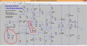
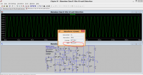
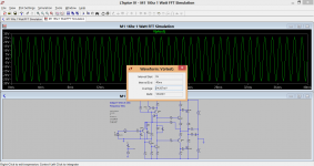
I am just re running the OLG sim again. Same set up for both as you can see.
Vin is 70.7uv RMS for both. Frequency is 1kHz.
Blameless Class B delivers 953 mv RMS into 8 ohms. M1 amplifier clips requiring the input signal to be lowered.
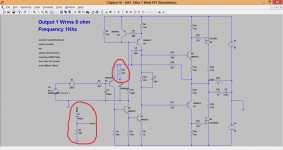
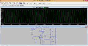
New input level for M1 is 34.8 uv. Output is now 18.6 volts.
Vin is 70.7uv RMS for both. Frequency is 1kHz.
Blameless Class B delivers 953 mv RMS into 8 ohms. M1 amplifier clips requiring the input signal to be lowered.
New input level for M1 is 34.8 uv. Output is now 18.6 volts.
Attachments
Looks like the next build. Thanks Raj.
Terry,
You are fantastic
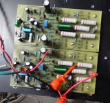
:Well I have it singing but it is not a very happy camper. I will have to do some more reading through the thread. I built it to the schematic in post #1 and the values on Alex's board which seem to match. The output doesn't look too bad with a load attached. A little over shoot on the square wave. The biggest issue is the offset. Once I play a sine wave through it the offset starts jumping all over the place and doesn't settle again unless I shut it down and restart. Any suggestions are welcome.
Also, the gains seems really low. With a 1.2v input I am only getting about 8.5V output.
Blessings, Terry
Also, the gains seems really low. With a 1.2v input I am only getting about 8.5V output.
Blessings, Terry
Attachments
Member
Joined 2009
Paid Member
- Home
- Amplifiers
- Solid State
- My MOSFET amplifier designed for music