My last post for today. I promise.
I went ahead and tried the OPA627 with the pin 2-6 compensation cap. Same configuration, input open, C9 and C13 shorted. Measured with George preferred Fluke.
Output - 1.97 VDC, 0.15 VAC. I have seen this level of AC before with open input, but I have yet to try with shorted input or balanced converter.
pin 3 - 6 = 620 mV
pin 2 - 6 = 74.5 mV
pin 2 - 3 = 0.1 mV
output - pin 3 = 74.5 mV
output - pin 6 = 1.7 mV
R10 = 73.8 mV
R11 = 0.2 mV
R13 = 72.5 mV should be 0.7 uA. For the OPA627, it should be 5 pA max input bias current.
So I still have a problem that changing the opamp didn't fix.
Good night all.
Jac
Given your results, I'd try a larger compensation value, maybe 10pF. If it improves offset further, or even fixes it completely, then that shows this is the area where the problem is.
Definitely worth a try. I found a 6 pF ceramic disc cap and paralleled it to the 5 pF already on the board. DC offset came down from 1.97 to 1.2VDC. AC is down from 0.15 to 0.1 VAC.
If the trend continued, I might get to an acceptable level at 20 to 30 pF, but it's probably not linear. I don't think I have any in that range. I will dig some more or try a 50 pF.
I have been through the board again and I feel like the circuit is working properly. The voltage gain is mainly in the opamp and the gain level is correct. The biggest problem is that we have about 200 mA running through R11 to ground, and with gain, it works out to approximately my DC offset. Since I can't find any other fault that would generate the current and because I have already changed the opamp without solving the problem, my next move may be to change the LM3886. It's possible I damaged it with ESD or too much soldering heat.
But first, I will try the compensation cap. If I remember, this reduces the bandwidth. I will have to read up on how much.
Jac
Wait a minute; too high a level of the OPA627 compensation cap and it enters an another regime of instability. Not good. up to 10-20pF ok.
I'm afraid that is not the root of the problem and just a treatment for troubles at some other origin.
let's think..
Maybe some photos..
I'm afraid that is not the root of the problem and just a treatment for troubles at some other origin.
let's think..
Maybe some photos..
George,
You are correct. I tried up to 30 pF and it started getting worse.
I agree that this isn't the source of the problem. By the way, when I short the input with 30 pF, the DC drops to 42 mV and the AC drops to zero. That has been pretty typical for this board in all conditions. I will remove the extra comp caps and keep it at 5 pF.
I can do pictures. What specifically would you like a picture of?
I am getting close to changing the LM3886 as a possible source of the DC current in the feedback loop.
Jac
")
So.. I had been always thinking how far this technology, Mauro's MyRef topology can be extended.. To admit it, this was even more spiced up by the latest developments in Tom's work. Hell, I always wished to do the same.. several current pumps in parallel connected in a bridged config..
Paralleling the pumps is important: recently I had executed a series of stress tests with single (FE style ) current pumps and with the full double pump configuration.
At high output levels and 4 ohm loads the difference is marked.
So without parallel pumps I would not dare to risk bridging. Or rather, it can be done but the results will not be nice.
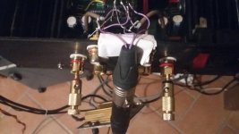
Then it came that it is so easy, in practice. The Evolution ampifier is a one pcb, stereo channels configuration with paralleled current pumps. One just needs that XLR input connector, drive in antiphase connection the two stereo sides and that's it.
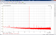
So here there are the test with a 'double barrel' EVO modul as directly connected with two XLR runs to the RTX6001 analyzer.
The analyzer is set to 10V/20dB output drive, and set to the 30dBV (31.6Vrms) input range.
This is just a modest first trial, moderate levels, because I'm using a low DC rails transformer. (+-28V)
The graphs are a bit different from the past format. I wanted to show the real output levels involved, so everything is calibrated to 0dBV reference output (= 1Vrms)
The output is crossed check with a multimeter, when I relieve 29,6dBV I see 30,4Vrms on the multimeter. (should be 30.2)
On 7.5ohm (I have that load, sorry.. it's even nice that it tollerates my tortures) that is ~ 120W.
At this level we are a hair below clipping, with this +-28Vdc transformer.
Paralleling the pumps is important: recently I had executed a series of stress tests with single (FE style ) current pumps and with the full double pump configuration.
At high output levels and 4 ohm loads the difference is marked.
So without parallel pumps I would not dare to risk bridging. Or rather, it can be done but the results will not be nice.
Then it came that it is so easy, in practice. The Evolution ampifier is a one pcb, stereo channels configuration with paralleled current pumps. One just needs that XLR input connector, drive in antiphase connection the two stereo sides and that's it.
So here there are the test with a 'double barrel' EVO modul as directly connected with two XLR runs to the RTX6001 analyzer.
The analyzer is set to 10V/20dB output drive, and set to the 30dBV (31.6Vrms) input range.
This is just a modest first trial, moderate levels, because I'm using a low DC rails transformer. (+-28V)
The graphs are a bit different from the past format. I wanted to show the real output levels involved, so everything is calibrated to 0dBV reference output (= 1Vrms)
The output is crossed check with a multimeter, when I relieve 29,6dBV I see 30,4Vrms on the multimeter. (should be 30.2)
On 7.5ohm (I have that load, sorry.. it's even nice that it tollerates my tortures) that is ~ 120W.
At this level we are a hair below clipping, with this +-28Vdc transformer.
Attachments
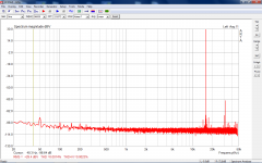

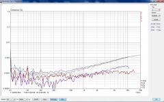
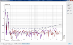
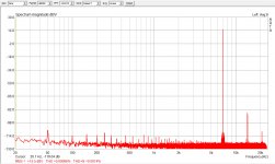
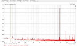
and these are the distortion sweeps with frequency.
The first is a middle value 36W output level.
The second at full throttle, just below clipping. (100W, because of constrictions in the software setting)
(in the low frequency range it does go into clipping, so there are those ugly walls towering.)
The first is a middle value 36W output level.
The second at full throttle, just below clipping. (100W, because of constrictions in the software setting)
(in the low frequency range it does go into clipping, so there are those ugly walls towering.)
Attachments
Last edited:
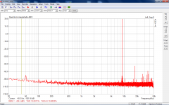
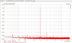
Just last two shots to show that at the usual 5W output level it is measuring almost exactly the same (at that moderate level I could change the RTX6001 output range for a less noisy setting: it does show that even the previous graphs we are limited in the noise floor by the analyser)
Attachments
Last edited:
Summary of my DC offset Issue
I built a pair of V1.2 boards with high quality, old BOM components, except the mods needed for Evo A and the ADA4627 opamp.
I had been stealing power for my balanced to single ended convertor from the regulated supply of the FE. That was OK with the LM318, but with the ADA4627 I had an oscillation that wasn't fixed by a compensation capacitor. So, I built a separate power supply and that solved it.
After the power supply, I still had an issue with DC offset, especially on one board. After swapping the ADA4627 to an OPA627, checking all components for good solder and value, replacing the LM3886, replacing some caps in the signal path, basically trying everything, the issue still exists on the one board.
The situation is that, when I have the input and C9 shorted, and C13 in place, I get about 1VDC offset on that board. If I replace C13 with a jumper and run DC coupled, the DC offset is manageable at roughly 30 mV.
Running DC coupled is OK for now and fine for evaluating the opamp change. But longer term, there is a potential risk of damaging speakers or other components. From initial listening, that may be worth some risk.
I suspect that the problem with DC offset is in the specific board itself and if I moved those components to a different board, I wouldn't have the problem. But that is just a guess.
In summary, I would like to make the following points.
- The FE is an excellent sounding amp as designed with the LM318. It is not necessary to make the change to the new opamps.
- The new opamps do offer a different, improved sound, but are sensitive and must be built and tested carefully.
- Always check DC and AC at the outputs with the input shorted before connecting to your "good" speakers. It's the first thing to do after your light bulb test proves you don't have any shorts. Of course, remove the light bulb tester before measuring.
Thank you for all your support. On to listening and tweaking.
Jac
- Home
- Amplifiers
- Chip Amps
- My_Ref Fremen Edition - Build thread and tutorial