Also, You are now in the Rev-C configuration.
It had it's merits but also Mauro had passed, later, to the Evo- revA configuration.
Part of that mod is the removal of C10, R39.
Particularly removal of C10 helps to achieve greater stability. So maybe it could be done here, too.
Removing C10, R39, as a partial 'revA' modification.
But first check carefully all these nodes.
i'm sorry if this is a stupid question, but how would i measure impedance over a capacitor? I checked all of the values you suggested and none of them are open or shorted if that is what you meant (for either board). I resoldered R37 and checked that there is a 3.3 kOhm resistance from the output of C30 to the input pin, which there was.
At the time that I bought the i did not realize that the revA had such an advantage so I just went for what i then thought was the 'standard' version, but in the future I will likely change it!
At the time that I bought the i did not realize that the revA had such an advantage so I just went for what i then thought was the 'standard' version, but in the future I will likely change it!
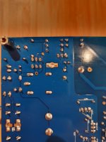
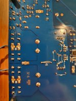
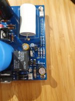
I have attached some better pictures of the board. I checked all the components, and all resistors have the right value, and all caps are at least operational. I'm not sure where to go from here
Attachments
Ok! I had to ask.. 😅
Why do you say that You can not measure on the board?
The fact that the relay disconnect - do not block You to measure between PGND & output tab..
Measure DC and AC.
Also the power supply (on the LM318 pins) would be good to see.
Although it does look like a bit of mistery.
Why do you say that You can not measure on the board?
The fact that the relay disconnect - do not block You to measure between PGND & output tab..
Measure DC and AC.
Also the power supply (on the LM318 pins) would be good to see.
Although it does look like a bit of mistery.
Haha please do ask, i totally see myself missing something like that...
And you are right ofcourse about the measuring
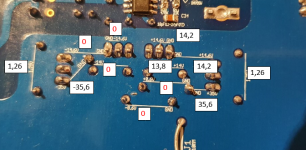
see attached for the values, and the value between the output and PGND was 31.6 V.
I think the left lm317 is faulty. But would that explain the behaviour I have been seeing?
thanks for the help so far by the way George it is really appreciated!
EDIT: I just checked and it appears Mouser shippen an extra one so very lucky there!
EDIT 2: changed lm318 to lm317...
EDIT 3: last one I swear the +0.6V is present (as opposed to the picture I made), and there is indeed no voltage on pin 4 of the LM318
And you are right ofcourse about the measuring
see attached for the values, and the value between the output and PGND was 31.6 V.
I think the left lm317 is faulty. But would that explain the behaviour I have been seeing?
thanks for the help so far by the way George it is really appreciated!
EDIT: I just checked and it appears Mouser shippen an extra one so very lucky there!
EDIT 2: changed lm318 to lm317...
EDIT 3: last one I swear
the +0.6V is present (as opposed to the picture I made), and there is indeed no voltage on pin 4 of the LM318Attachments
Last edited:
So I went through desoldering hell, and replaced the LM317, only to find out that that was not the issue
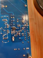
It looks like i have a solder bridge between the ground plane and the middle pin of T201 on the top side of the board... Only issue is that it is completely unreachable with a soldering iron... does anyone have any tips on how I would fix this? (preferably without desoldering any components)
It looks like i have a solder bridge between the ground plane and the middle pin of T201 on the top side of the board... Only issue is that it is completely unreachable with a soldering iron... does anyone have any tips on how I would fix this? (preferably without desoldering any components)
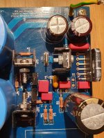
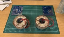
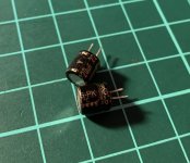
Almost ready to start:
A pair of 200VA 2x22V transformers.
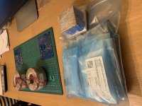
Industrial BOM (from Digikey US)
Pair of BG PK 220/4. I’ll hold them until I finish testing with Nichicon KZ.
And of course a pair of beautiful PCB from Dario
A pair of 200VA 2x22V transformers.
Industrial BOM (from Digikey US)
Pair of BG PK 220/4. I’ll hold them until I finish testing with Nichicon KZ.
And of course a pair of beautiful PCB from Dario
Attachments
Cool! Have fun, I advise to carefully check for solder bridges
I did manage to fix mine eventually after a lot of frustation. In the end i just completely desoldered the transistor and put it back afterwards.
Both boards are now operational and i have measured offsets of 3.2 mV, and 5,2 mV on the outputs (with unshorted inputs). And with some speaker wired up there is a slight hum.
I will start to put together the housing now, I will update with pictures when there is progress!
Thanks for the help so far!
If Dario does not have the newest boards for you, you may consider my offer in swap meat FS: My_Ref Fremen Edition PCB kit.
Regards,
Oleg
Regards,
Oleg
C9...
Hi,
I wanted to ask Dario and anyone who has experimented on the components, if you have ever tried a low leakage capacitor, like Nichicon UKL, in position C9. In the restoration of 70's amplifiers, at the beginning I used the usual audio grade capacitors like silmic, kz, kg, kw, cerafine on the pre and phono boards.
When I found out that those orange elnas on these boards were low leakage, I tried using the UKL with very interesting results. Unexpected for a capacitor not very considered in audio.
I know I'm talking about an experience on old amplifiers that used low leakage capacitors in certain positions and therefore using the same type works very well. But I got the curiosity.
Thank you all
Ciao
Giacinto
I have tried lots of different capacitors at C9 (but not as many as Dario, I'm sure), but never UKL. I even tried Niobium capacitors there. The FE is very sensitive to C9, so it would be worth a try.
I would argue that the best cap at C9 is no cap, which is why Mauro explored DC servos on the EVO. Of course, DC servos have their impact on sound too.
Remember that the reason for C9 is to reduce the gain of the amplifier at DC, but it is part of the signal path for the whole frequency range.
I would argue that the best cap at C9 is no cap, which is why Mauro explored DC servos on the EVO. Of course, DC servos have their impact on sound too.
Remember that the reason for C9 is to reduce the gain of the amplifier at DC, but it is part of the signal path for the whole frequency range.
- Home
- Amplifiers
- Chip Amps
- My_Ref Fremen Edition - Build thread and tutorial