hi just a guy - when making tapped pipes with mouth area less than Sd, which of the three shapes below (assuming ~equal area) is most desirable? - or are they functionally the same?

IMO They will all produce slightly different results as they move the position of the mouth with respect to the driver (and the rest of the horn).
In post # 1492, “Single sheet TH challenge”, Crescendo measured his 3015LF loaded, 1/2” Aruco plywood SS15 cabinets outdoors: 70Hz: 103.2 dBC, 2.83 v at one meter, 70Hz, 124.7dBC, QSC PLX3402 amplifier “just at clip” (about 75 volts, 700 watts at 8 ohm). Had there been a linear voltage in/SPL out relationship, 700 watts/75 volts would have resulted in about a 28.5 dB increase in SPL, 131.7 dBC.
131.7-124.7 = 7 dB of power compression. Ouch.
I suspect that those measurements might be a little off, and the 7dB difference may be more due to the measurement technique rather than just power compression.
I did a similar test on my POC3 TH today. The results seem to show little or no compression all the way up to the point that driver excursion was becoming a limiting factor. The SS15 is at least double the volume of my POC3 and uses a much more capable driver. The only thing I don't really like that much about the design is that it doesn't seem to be braced enough (I'm still waiting for someone to post up an impedance curve measurement for their SS15 to confirm whether or not this is the case).
This appears (modifying the way they define the TH in the picture JAG showed me) to be "as designed". Measured roughly using solidworks to guestimate midpoints/arcs, should be good to within ~10% on l23 and pretty accurate elsewhere. Going to work on making this "more ideal" by mainly shortening the path.
Attachments
I suspect that those measurements might be a little off, and the 7dB difference may be more due to the measurement technique rather than just power compression.
I did a similar test on my POC3 TH today. The results seem to show little or no compression all the way up to the point that driver excursion was becoming a limiting factor.
7db does seem like quite a lot of loss, "ouch" indeed! So either the measurements are flawed like you say or the Kappalite 3015lf has performance issues under the high pressures of horn loading like WelterSys suggested it probably would based upon his experience with the Definimax 15.....
I specifically remember some shootout results from a few years ago that involved BFM's T48 boxes loaded with Kappalite 3015LFs which raised cause for concern... When they compared response curves at different power levels the high rate of compression became very apparent... I have to wonder if loading a more robust driver into those T48s would have solved the issue..
Thats GREAT news about your POC#3 Brian , congrats
") Sounds like that design was a success! .....
Sounds like that design was a success! .....I am curious about what sorts of results you might get when running that same compression test on the POC#2. ?
Hornresp really like multiple drivers in this "size", now to figure out how to mount multiples most efficiently.
Scratch that idea. I just realized that I can shorten this to ~39 inches tall external and get a 38 Hz tune that helps 35-50 considerably more than the 32 Hz tune I had previously spec'ed. Before after in attached image.
External size 17.5 wide 20.25 deep 38 tall
After the "peaks" smooth out a little bit as I expect should be looking at 121-123 dB full spectrum (33-100) with an extra 5 mm xmax to spare (out of thermal power at this point) only a 25 Hz HP 2nd order and 100 Hz LP (4th order) to keep exursion/response looking good.
Posting hornresp file in case I screwed up L34, being a flat mount I assume these to be equal, check me on that.
P.S. I assume that anywhere these are being used will have parametric equalization so flat response is less important to me.
Attachments
Last edited:
Found some leaks on my alpine sub, needless to say they are being filled by PL/drying now. Didn't expect the screws I used to hold the brace in place to be problematic, shouldn't be a problem anymore. Not doing any more "restricted" builds for me short term, going to work with this tapped pipe topology because I like the simplicity and well screw port compression (having to consider it).
If we look at the Keystone thread at only 271 posts compared to the SS15 thread at 2069 posts, the Keystone is 8.8 dB down ;^).
Art
HAHAHA! Nerd humor at it's best!
Thank you for that "Lightweight cones work fine under the lower pressures in a BR, but may not be up to the task in designs that leverage output by 6 dB, though it does not seem to bother people that that 6 dB increase may be lost at actual use level"
"The BC18SW115-4 Keystone hardly has any power compression, and a fraction of the distortion of a lightweight cone driver in the SS15, but few seem to notice those pesky details
Art
So, (If i am understanding correctly) from your experiences and observations you have concluded that the primary reason that the Definimax 15 performing poorly in your Keystone was the lightweight cone or lack of cone strength? right?
If this is true, then i am really glad that i didn't try to build a 40hz Tapped Horn around the B&C 18PS76 driver ..... It sims very well, but according to what you are saying it may not work well in reality ..
In your opinion are these light cones not acting as proper pistons under pressure? are they warping?
3) Saba's indoor response curves may not be indicative of the actual cabinet response at different levels, I would not make any speculations unless outdoor tests away from boundaries showed similar response deviations.
Art
Yeah, I am taking it all with a grain of salt since the measurements were taken under less-than-ideal conditions ... Intriguing nonetheless.... I would prefer a little bit of loss at 80hz (at high SPLs) instead loss at 40hz, and the results should have shown exactly the reverse of what we see in the graphs (if these losses were truly due to excess particle velocity at around FB) ..... It calls into question the official understanding of how this all works..
That would be great if you could post the inputs, I think the alpine 15 should work for that kind of alignment.
Sidenote: why couldn't you just make the box deeper to accomodate the lab 15? I see no reason why you couldn't do that.
Saba,
The box had an internal volume of 144 liters already and i didn't want to make it any bigger, i like to sim with the goal of maximum decibels out of a quarter wave based design in the smallest (easy-to-build) package as is possible with the least amount of money spent and thats why i like the smaller Alpines so much, they are hard to beat in that respect .....
Their parameters also happily support pipe boxes with little to no expansion or even reverse tapers which works well for what i am trying to achieve ....
You were trying to design something for the SWS-15D correct? If your target FB is still 35hz the 15 would not be a good choice .... Your driver FS needs to equal or exceed (up to 1.6x) your cabinet's FB in these sorts of designs and the sws-15 has an FS of 27hz so that is not the best driver for you to go with , i would suggest 2 of the 10s or two of the 12s in either the SWE or SWS line, depending on how much power handling and displacement you are aiming for ....... The Eminence Lab15 (special) also would be a good choice for 30hz to 35hz and it is in the same price range as some of the others you were looking at ..
Last edited:
..... It calls into question the official understanding of how this all works..
A couple of uncontrolled, uncalibrated in room measurements of a box that has air leaks at unknown power levels doesn't call into question the official understanding of how this works.
There is a huge multi billion dollar industry that relies on properly sizing ducts. HVAC system designers use friction coefficient, reynolds number, kinematic viscosity info, etc to calculate boundary layer effects to properly size their ducts for low losses. They know what they are doing.
The loudspeaker industry has a pretty good idea what they are doing too, at least in the upper levels of the industry. They do actual scientific research and collect data like this:
An externally hosted image should be here but it was not working when we last tested it.
... and this ...
An externally hosted image should be here but it was not working when we last tested it.
From this AES paper by guys working at JBL and Infinity - http://koti.kapsi.fi/jahonen/Audio/Papers/AES_PortPaper.pdf
They aren't guessing, the official understanding of how this works is fine.
I said a long time ago that my analysis might be wrong but until we see some measurements I'm sticking to my story because I'm just reporting what the software is saying. Akabak and Flare It, neither of which are notoriously inaccurate.
IMO They will all produce slightly different results as they move the position of the mouth with respect to the driver (and the rest of the horn).
I agree. Hornresp assumes the mouth is always right at the end of the line. In the middle picture, the circular port is creeping up the backside of the cab like an offset MLTL port, that's going to mess with your simulated response.
As far as velocity issues, just make sure the mouth is big enough and the aspect ratio is not ridiculously high and that's really all you can do.
Saba,
The box had an internal volume of 144 liters already and i didn't want to make it any bigger, i like to sim with the goal of maximum decibels out of a quarter wave based design in the smallest (easy-to-build) package as is possible with the least amount of money spent and thats why i like the smaller Alpines so much, they are hard to beat in that respect .....
Their parameters also happily support pipe boxes with little to no expansion or even reverse tapers which works well for what i am trying to achieve ....
You were trying to design something for the SWS-15D correct? If your target FB is still 35hz the 15 would not be a good choice .... Your driver FS needs to equal or exceed (up to 1.6x) your cabinet's FB in these sorts of designs and the sws-15 has an FS of 27hz so that is not the best driver for you to go with , i would suggest 2 of the 10s or two of the 12s in either the SWE or SWS line, depending on how much power handling and displacement you are aiming for ....... The Eminence Lab15 (special) also would be a good choice for 30hz to 35hz and it is in the same price range as some of the others you were looking at ..
Mainly looked at the 15 because of the increased displacement, I realize it's low FS makes it less ideal (less flat) but the overall displacement intrigued me. I'll try out the 12 inch version and 10 inch version in straight pipes.
Saba,
The box had an internal volume of 144 liters already and i didn't want to make it any bigger, i like to sim with the goal of maximum decibels out of a quarter wave based design in the smallest (easy-to-build) package as is possible with the least amount of money spent and thats why i like the smaller Alpines so much, they are hard to beat in that respect .....
Their parameters also happily support pipe boxes with little to no expansion or even reverse tapers which works well for what i am trying to achieve ....
You were trying to design something for the SWS-15D correct? If your target FB is still 35hz the 15 would not be a good choice .... Your driver FS needs to equal or exceed (up to 1.6x) your cabinet's FB in these sorts of designs and the sws-15 has an FS of 27hz so that is not the best driver for you to go with , i would suggest 2 of the 10s or two of the 12s in either the SWE or SWS line, depending on how much power handling and displacement you are aiming for ....... The Eminence Lab15 (special) also would be a good choice for 30hz to 35hz and it is in the same price range as some of the others you were looking at ..
Reason I'm not buying into the lab 15 is it is a limited run, I'm trying to design a box that can be replicated 6 months from now... Plus I don't have the money on hand to stockpile them
.A couple of uncontrolled, uncalibrated in room measurements of a box that has air leaks at unknown power levels doesn't call into question the official understanding of how this works.
There is a huge multi billion dollar industry that relies on properly sizing ducts. HVAC system designers use friction coefficient, reynolds number, kinematic viscosity info, etc to calculate boundary layer effects to properly size their ducts for low losses. They know what they are doing.
The loudspeaker industry has a pretty good idea what they are doing too, at least in the upper levels of the industry. They do actual scientific research and collect data like this:
An externally hosted image should be here but it was not working when we last tested it.
... and this ...
An externally hosted image should be here but it was not working when we last tested it.
From this AES paper by guys working at JBL and Infinity - http://koti.kapsi.fi/jahonen/Audio/Papers/AES_PortPaper.pdf
They aren't guessing, the official understanding of how this works is fine.
I said a long time ago that my analysis might be wrong but until we see some measurements I'm sticking to my story because I'm just reporting what the software is saying. Akabak and Flare It, neither of which are notoriously inaccurate.
Ran some medium power 30 Hz tests (to find leaks, which are now sealed) and there was some notable "turbulence". I find it very likely that JAG's on the right track as far as compression, but as i've said before I've given up on examining it further since I don't have the tools to do so and will be abandoning the design after this build is complete (most likely tomorrow the second will be done).
P.S. I'm going with straight pipes now because IMO 13 m/s (what it currently simulates in the mouth) will have no "port compression" considering the whole so called duct is 9x16 inches
.Compact PP ML-TF using W5-876SE's
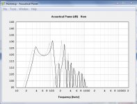
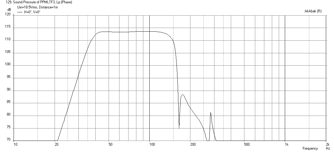
I came up with a design using this alignment for the 5 inch Tang Band W5-876SE drivers. It is a push pull design so that 2nd order distortion is reduced. The drivers are 16 ohm so putting them in parallel gets 8ohm nominal load. The box size is 16in x 16in x 12in (external). Here is the predicted max SPL freq response in corner loaded setup:
More info here:
http://www.diyaudio.com/forums/subwoofers/258433-light-air-slot-loaded-band-pass-sub-8.html#post4032728
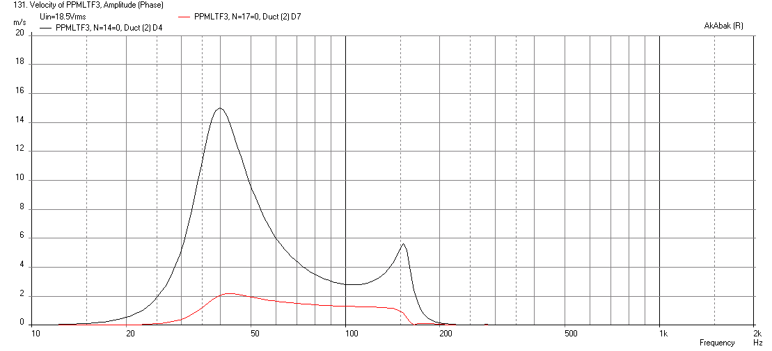
Also, no chuffing here to worry about, here are the velocities:
I came up with a design using this alignment for the 5 inch Tang Band W5-876SE drivers. It is a push pull design so that 2nd order distortion is reduced. The drivers are 16 ohm so putting them in parallel gets 8ohm nominal load. The box size is 16in x 16in x 12in (external). Here is the predicted max SPL freq response in corner loaded setup:
More info here:
http://www.diyaudio.com/forums/subwoofers/258433-light-air-slot-loaded-band-pass-sub-8.html#post4032728
Also, no chuffing here to worry about, here are the velocities:
12 inch sims to the following dimensions, 13 wide 16.5 deep, 39 tall, 118.5db trough at 69 123db peek at 38
Slightly flatter FR
Essentially 2 dB less overall. just under 5 cu. ft., compared to the 7.8 cu. ft of the 15 inch loaded one.
Requires 29 HZ hp at 4th order or higher freq.
Slightly flatter FR
Essentially 2 dB less overall. just under 5 cu. ft., compared to the 7.8 cu. ft of the 15 inch loaded one.
Requires 29 HZ hp at 4th order or higher freq.
Last edited:
So.... I just bought a sws 12 d4 for 73 including shipping. Damn that's a steal of a price. Couldn't pass it up, finishing my 2nd alpine swe10s4 build tomorrow most likely so this should arrive just before I head home for a couple weeks (shipping from california to california).
Going to throw it in the pipe box I mentioned here, if anyone is interested i'll post details. Hoping for no port compression (no port to compress so should be fine there) and limited driver compression. Should be seeing pretty solid 122db or thereabout measured ~40 Hz if things go to plan and assuming I can find a 500 watt amp to power it (IMO that's very good for 4.8 cu. ft).
Going to throw it in the pipe box I mentioned here, if anyone is interested i'll post details. Hoping for no port compression (no port to compress so should be fine there) and limited driver compression. Should be seeing pretty solid 122db or thereabout measured ~40 Hz if things go to plan and assuming I can find a 500 watt amp to power it (IMO that's very good for 4.8 cu. ft).
You can build a 4.00 cu. ft box as an alternative that gets 38 Hz extension with >118 dB output 38-100 (peaking at 123 at 45 Hz) for the sws 12s4. Thats 14.5wide 13.75 deep 35 tall external. Granted you have to face the driver cone out to fit, that still is one heck of a compact box.
Keep in mind this does have a peak air velocity of 16 m/s at 44 hz, a little higher than the 13 m/s of the larger box.
Keep in mind this does have a peak air velocity of 16 m/s at 44 hz, a little higher than the 13 m/s of the larger box.
Last edited:
SABASPEED ,
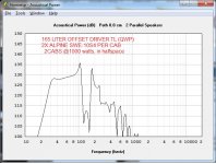
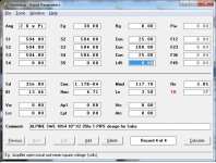
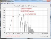
Take a look , i put some sims together for you .... All non-tapered/non-expansion pipes ... Single fold sort of stuff , very simple ... very effective .... All tuned to 35hz.
I used the 10s in these, but could be scaled up to work with 12s...
The tapped-pipe version is compact, and the Offset Driver Quarter Wave Pipe is significantly larger with more output according to sim ..
Attachments
Sabasped,
I also wanted to say thanks for giving the ML-Transflex a try ....I am looking forward to any more measurements or observations you might have about it, although i am now numerous revisions along now so i think i have sorted out the (potential) issues with the design, newer versions do have lower particle velocity (not that it was ever proven to be a problem with these) but i heeded the warnings of our concerned Canadian friend and made some improvements just to be safe ...
To be honest though i think the whole velocity topic ended up being overblown (bad pun , hehehe) ......
Constrictions, ports, and vents have been used for ages and still are being used as abundantly as ever in respected speaker cabinets in all apps (pro , home, car, as in Bass Reflex etc etc) and they are incredibly useful if executed properly.... There were examples given here in this discussion that moderately raised particle velocity rates don't NECESSARILY equate to lost output (relative to the rest of the spectrum) at high power in the range where particle velocity peaks (supposedly near or just below FB according to sims) .. It would be fun and interesting to see even more examples of this to try to figure out if it only applies to certain types of cabinets or situations ....
Saba , I hope you will be able to more high/low power comparisons again now that you have sealed up those unsavory leaks you have recently discovered because it would be nice to be able to rule out their influence
Last edited:
SABASPEED ,
Take a look , i put some sims together for you .... All non-tapered/non-expansion pipes ... Single fold sort of stuff , very simple ... very effective .... All tuned to 35hz.
I used the 10s in these, but could be scaled up to work with 12s...
The tapped-pipe version is compact, and the Offset Driver Quarter Wave Pipe is significantly larger with more output according to sim ..
Just wondering how do you mount the two drivers in both these cases, and what does the one on the left look like (I've cad'ed out the straight pipe as I've shown in an image but the other I'm not sure what it looks like and/or the build complexity).
Thanks a bunch, those are some crazy good sims and they are better than mine on the compact end
. If it's not too much I'd be interested in what a single and dual 12 sws 12d4 would look like size wise and output wise (in the same style of the one's you did).Here are the sws 12 specs
15 mm xmax 500 watts rms
479 1.34 E-04 157.48 7
20.19 3.7 4.84
That's the same format as hornresp in the correct units.
- Home
- Loudspeakers
- Subwoofers
- New sub design? Constricted Transflex, simple build (series tuned 6th order)