Again, "performing poorly" is relative, lightweight cones are more sensitive than heavy cones, if power is limited, they can be a good choice.So, (If i am understanding correctly) from your experiences and observations you have concluded that the primary reason that the Definimax 15 performing poorly in your Keystone was the lightweight cone or lack of cone strength? right?
In your opinion are these light cones not acting as proper pistons under pressure? are they warping?
Given most cone material is largely pulp paper, thin light cones "cave in" under less pressure than thick heavy cones. All the simulation programs assume a rigid flat piston, but under high power, a cone is not, it starts to deform. The sensitivity advantage of a light cone may not hold up under pressure, as the bending of the cone progressively absorbs power. Given adequate power, especially below Fb, the deformation can be permanent, resulting in "tenderized", kinked, or ripped cones. "Curvilinear" cones like the Eminence 3015LF, or the old EV15L, designed for more extended upper response, are more likely to deform under pressure than straight sided cones.
The only way to determine how little MMS is acceptable in a given design is to actually measure it for distortion and compression at the drive levels it will be used in practice, 2.83 volt response may be fine for the home, but if you will be using it at 40, 60, or 120 volts, see what happens.
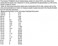
Another area where simulations differ radically from measured reality is in the assumption that the driver suspension is a linear system, when it is not, as can be clearly seen in the measurements below, where predicted excursions differ from measured by huge amounts. Additional sweeps were conducted at 76 volts, maximum excursion measured was 17.5mm (one way), while Hornresp predicted 26.97mm at 22 Hz and 46.46mm at 4 Hz.
Given that the Flare-it program JAG has used requires four velocities entered from the design software (of your choice) to automatically find the minimum flare radius required, and the fact that no simulation accurately predicts real world excursion, (especially below Fs) it is doubtful results will match it's predictions.
Art
Attachments
Last edited:
Given that the Flare-it program JAG has used requires four velocities entered from the design software (of your choice) to automatically find the minimum flare radius required, and the fact that no simulation accurately predicts real world excursion, (especially below Fs) it is doubtful results will match it's predictions.
Art
If you enter the 4 velocities from the design software of your choice THAT CAN SIMULATE VELOCITY WITH A HPF IN PLACE if one is going to be used in reality (which narrows your choices to only Akabak for the Shoehorn and MMJ's designs), the results should fairly accurately represent reality with the caveat explained below.
As both you and GM have pointed out the sim software will usually overshoot in it's estimation of some things like excursion and velocity. So clearly the results of my analysis with Akabak and Flare It will be on the conservative side and I keep that in mind but it's good that you mention it. This is why I called your Shoehorn ports only "moderately" undersized even though Akabak predicts 31 m/s with hpf in place and Flare It says 18 m/s is safe. Clearly the Shoehorn is exhibiting some amount of compression so I think it's more than fair to say the ports are moderately undersized.
Last edited:
Most household circuit breakers are capable of passing ten times their rating for brief periods of time. A 15 amp 120V circuit can deliver 1800 watts, so peaks of under 18,000 watts may not trip the breaker. Most class D amplifier circuit breakers have a faster time constant than household breakers.Unrelated but on the note of dual loading: how much power can you get from a 15 amp outlet (to the driver), assume class D amplifier like maybe a inuke or newer crowns.
1,000 watts per cab is nice and all but I don't know if you can actually get 2000 watts from a standard outlet, assuming your amp has that much current capacity.
15 amp outlets may be wired with only 14AWG wire, depending on the distance of the wire to the main power transformer, voltage drop may be extreme under peak demands, limiting amplifier output power.
Although an outlet may read 120 VAC when unloaded, different amp designs will “brown out” (dropping to 110V or even less) the service on peaks to a different degree, some amps that perform just fine on bench regulated 120V power don’t behave at all well in the real world of lower voltage at higher amperage peaks.
When doing full power <2 ohm testing using the Speakerpower SP 4000 (probably among the most efficient class D amps available), it would dim the compact fluorescent shop lights on each kick drum beat, running on a 10AWG circuit approximately 120 feet from the service transformer. Under full power 2 ohm sine wave testing (4000 watt output) it's internal 18 amp breaker would pop after about 3 seconds, IIRC.
Last edited:
"Again, "performing poorly" is relative, lightweight cones are more sensitive than heavy cones, if power is limited, they can be a good choice."
"The only way to determine how little MMS is acceptable in a given design is to actually measure"
"Another area where simulations differ radically from measured reality is in the assumption that the driver suspension is a linear system, when it is not, as can be clearly seen in the measurements below, where predicted excursions differ from measured by huge amounts. Additional sweeps were conducted at 76 volts, maximum excursion measured was 17.5mm (one way), while Hornresp predicted 26.97mm at 22 Hz and 46.46mm at 4 Hz."
Art
Art ,
I did see this list of XMAX measurements recently and i found it highly interesting because it doesn't seem to follow the pattern that is normally seen in a vented simulation at all , i cannot even easily determine where the FB is by just looking at that list, but in simulation it would be very easy to spot ..... It is a fantastic example of how virtual operation modeled in software can be very different from real-world results ...
Just out of curiosity was this measurement done in your small PPSL cabinet? or something else?
Given that the Flare-it program JAG has used requires four velocities entered from the design software (of your choice) to automatically find the minimum flare radius required, and the fact that no simulation accurately predicts real world excursion, (especially below Fs) it is doubtful results will match it's predictions.
Art
ART ! OH MY GOSH, please be careful man, that sort of dangerously blasphemous suggestion tends to get certain Canadian people terribly wound up! After all we know that software like Flare-It is unquestionably omnipotent and is composed of holy divine code created in a collaborative effort between The Pope, Budda , Krishna, Baby Jesus, Allah, Yahweh and Carl Sagan .............................. To suggest (heaven forbid) that it is anything less than perfect (in every imaginable scenario and application) is an unforgivable HERESY!
") ....... how dare ....... with your real world measurements *glare*. .................. bah!.............................................. HAIL SAGAN!
....... how dare ....... with your real world measurements *glare*. .................. bah!.............................................. HAIL SAGAN!
Last edited:
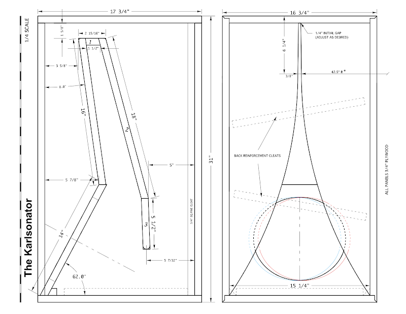
Now that you mention Karlsonator, I do think that GregB's excellent design is indeed a ML Transflex 6th order bandpass alignment. It is used to extend bass of a fullrange driver rather than as a sub, but looking at its topology, it is exactly the same with the benefit of Karlson aperture on the exit. I have a model of the Karlsonator in AkAbak and never bothered to check the velocities in the constriction because we never have an issue with reports of chuffing.
XRK,
Thanks for this! and the links .... The Karlsonator definitely looks like a fine piece of functional art with it's lovely K aperture, modern performance with a nostalgic appeal right? Internally i suppose it is much like Brian's POC#2 box having an expanding path with the constriction at around 2/3rds of the way down the path from the closed end, except the driver in the Karlsonator looks somewhat offset instead of right near the beginning of the path... The offset could have it's benefits depending on the driver used , in addition to helping tame the 3rd pipe harmonic to some degree i suppose ...
X , do you happen to have any measured response charts for any Karlsonator cabinets with an FB of between 30 and 50hz? I am just curious about how prominent the response dip is just above the 3rd harmonic on those designs ....
Something elseArt ,
Just out of curiosity was this measurement done in your small PPSL cabinet? or something else?
As stated, the 15" Dayton PA385-8 excursion measurements were open air, as was the simulation, done as an open baffle equal to Sd.
But that driver will be an outlier when compared to drivers with more linear suspensions

TheJessman built a Karlsinator 12 for Freddi and measured the response. It is in either mini Karlsonator thread or Karlsonator thread prioper. Do search for TheJessman. I think standard 12in Karlsinator is tuned for fb of 40Hz. I am running some sims now with the Lab15 in a 1.5x scale in L and , 1x in W Karlsinator and indeed it works very well with flat from 30Hz up with small dip at 100Hz but smooth after that to 2kHz - not high peaks or ripples - the benefit of the K aperture.
anyone else excited as i am to test out the sws pipe? In fact, I'll post a fully labeled side view so anyone with akabak that doesn't mind simming it can give me a better picture of what "actual output" I should be looking at both in a corner and open space (ground plane).
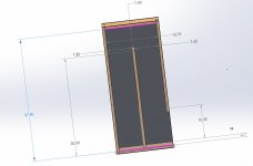
And... here it is. 39x17.25x14.5, 5.6 cubic feet, a little bigger than I thought it was (previously must have confused internal/external). This is accurate.
damn recalculated path length and it's not quite enough... L23 is center of chamber path distance center of driver to other side of center of driver right?
Attachments
Last edited:
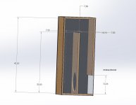
Well the previous post needs some modification, did a more accurate path length calculation and my previous simulation was in the 140 cm range (l23) whereas I need ~180. Below is the 178 cm path length version, 42 inches tall, rest unmodified.
What driver is this for? Should be pretty straightforward to model.
What driver is this for? Should be pretty straightforward to model.
sws 12 d4, I put the ts params a few pages back (i think 2 but not sure) also here is the spec sheet.
http://support.alpine-usa.com/products/documents/OM_SWS-101215_D4_2.pdf
Assume series voice coils. (8 ohm nom, 7 ohm re)
Another area where simulations differ radically from measured reality is in the assumption that the driver suspension is a linear system, when it is not, as can be clearly seen in the measurements below, where predicted excursions differ from measured by huge amounts. Additional sweeps were conducted at 76 volts, maximum excursion measured was 17.5mm (one way), while Hornresp predicted 26.97mm at 22 Hz and 46.46mm at 4 Hz.
I think there's a problem in your measurement procedure, well at least if you're trying to compare the measured results to what HornResp or other box-modelling programs predict in that scenario. Hint: what happens to a driver's voice coil when you drive 45 or 76 volts continuously through it?
In Brian's case it was a novel and inventive way to fix a problem. I don't think it's a good idea to use the concept as a design feature in a new design.
It was effective and didn't appear to cause any problems, so why not implement it? ....The box performed well, had extended bandwidth (for a TH) and Brian says there was no audible chuffing.... So once again , why not?...
The way in which his carefully placed constriction filled in the midbass dip is fascinating and implies something special is going on there, perhaps an additional resonance being created? *shrug* I think it is something worth looking into, developing a more thorough understanding of whatever is going on there could help advance the art/science of cabinet design ...
IMHO i dont think that Brian's DFD discovery was ever given enough attention and i never really heard much of anything about people following up on it with other builds..
"The reason is not that it doesn't compress, his tuning is high and his port output is very blunt and broadband so it's very hard see the compression effects. You HAVE TO go outside the passband a bit to see that there is actually significant compression happening because inside the passband it's happening everywhere, not just a Fb."
" The theory and/or physics of the compression phenomenon does not break down in the Shoehorn"
Unfortunately going out of the passband gives you results that are meaningless because you aren't going to be using it there, and to insist that there is a broadband port loss is an assumption on your part ...
To suggest that port behavior may vary to some degree in different designs isn't the same as saying: "physics is breaking down", which is just being ridiculous of course, and i never said it, nor have i implied it, physics assuredly would still be at play as much as it ever is but there may be factors that software is not taking into account ...
There is no need to misquote or distort the spirit or the letter of anyone's statements here but i can chalk this up to misinterpretation on your part and leave it at that ...
At one point or another you did actually say each of those things and you seem to maintain that there are real world examples that don't adhere to the laws of physics. Small ducts introduce losses, there's no way around that.
I have said many things like Ideas, theories, hypotheses, notions, impressions for the sake of discussion , learning and exploration of concepts because I highly value the feedback and responses from all of the big brains on DIYaudio, this is a truly great resource! So if i happen to say something such as: "Is It possible that software might be missing some factor? or Could it be that there is something going on here that we don't yet understand? Notice that i am not insisting on some fact by any means i am just commenting on something i observed or i am asking a question, and i am looking for feedback, ideas, suggestions and opinions because i seek to broaden my understanding on a subject, and i thought that much would be obvious (due to my wording)..
Regardless of your impression of me i am really not some sort of fundamentalist zealot that holds unfounded or theoretic ideas near and dear to my heart as i force those same ideas upon an unwilling populace, shoving my rigid dogmatic beliefs down the throats of innocent nerds on sound forums disrupting discussions scaremongering, trolling and beating dead horses until nobody can even stand to read the words "Particle velocity" and "port compression" one more time .............................
Thats just not me at all ..... Not even close ............ ehem
JAG , we are all VERY aware of the Port-Velocity/Compression relationship now ... Your mission has been fully accomplished, good job, thank you , changes have been made, we have learned some things, so can we please move on now? There are a multitude of other design aspects that we could cover and it is counterproductive to be so overly focused on just one aspect ...
I propose that we try to get back to having a reasonably well rounded and productive discussion ..
Last edited:
Brian,I think there's a problem in your measurement procedure, well at least if you're trying to compare the measured results to what HornResp or other box-modelling programs predict in that scenario. Hint: what happens to a driver's voice coil when you drive 45 or 76 volts continuously through it?
Since the open air impedance was generally quite high (at least according to the sim), not much heat was generated at 56.4 volt input, the magnet structure had hardly any increase in heat after testing (even after applying 76 volts), though a slight rise could be felt around the dust cap. Believe me, I know what drivers suffering from thermal compression feel like, of course box-modelling programs ignore thermal compression issues as well as suspension and BL non-linearities.
At any rate, this was the first time I had done extensive open air excursion measurements, what are you suggesting was the problem in my measurement procedure?
Art
Last edited:
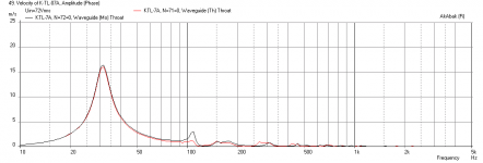
Karlsonator scaled to 1.5x with Lab 15
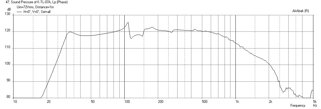
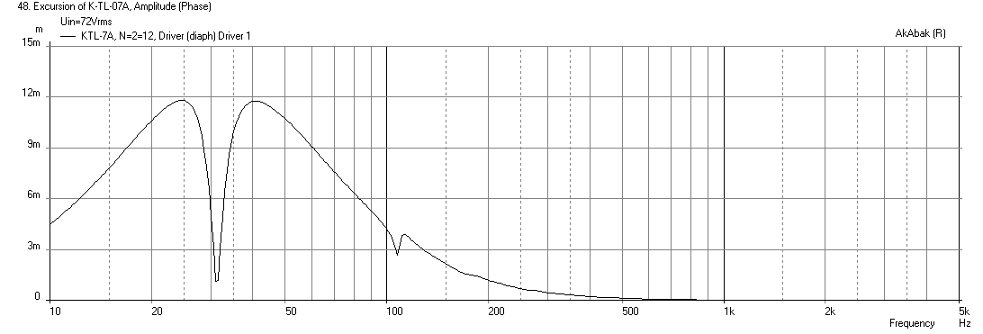
Here is the Karlsonator, scaled to 1.5x high and deep and 1.1x wide with a Lab 15 8 ohm. That is a 45 in tall x 17 in wide x 24 in deep This is for 2 pi sitting on floor.
Max SPL at 72v with -12dB HPF at 31.5Hz:
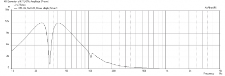
Cone Displacement:
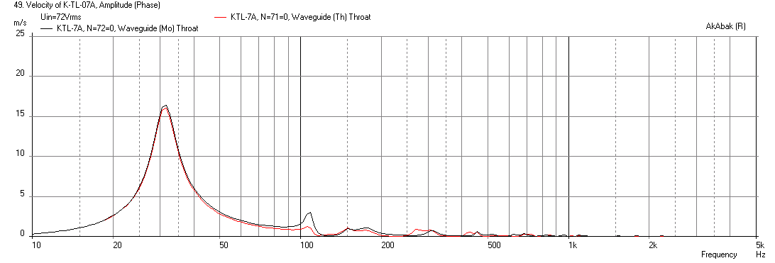
Max throat velocity is 17m/s, I think chuffing is not an issue here:
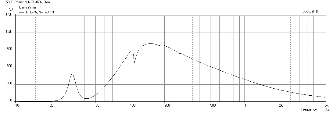
Electrical power (1kW if you want it to serve as high bandwidth driver with no LPF) but very efficient if high-passed below 100Hz:
I think that this actually looks pretty impressive for a sub to be able to reach such a high bandwidth of 1kHz smoothly. The reverse taper ML-TQWT with 6th order bandpass seems to work well. Like I said, the K-nator box is very versatile and easily scaled for just about any driver.
Here is the Karlsonator, scaled to 1.5x high and deep and 1.1x wide with a Lab 15 8 ohm. That is a 45 in tall x 17 in wide x 24 in deep This is for 2 pi sitting on floor.
Max SPL at 72v with -12dB HPF at 31.5Hz:
Cone Displacement:
Max throat velocity is 17m/s, I think chuffing is not an issue here:
Electrical power (1kW if you want it to serve as high bandwidth driver with no LPF) but very efficient if high-passed below 100Hz:
I think that this actually looks pretty impressive for a sub to be able to reach such a high bandwidth of 1kHz smoothly. The reverse taper ML-TQWT with 6th order bandpass seems to work well. Like I said, the K-nator box is very versatile and easily scaled for just about any driver.
Attachments


Last edited:
Hey guys just wanted to mention that I'm letting the last panel glue onto the second swe10s4 build. Should be able to power tomorrow or even tonight late.
Just wanted to give a subjective review of the "other swe10s4 build,
the one that should be leak free now", let's check on that. --->
Anyways, I've driven it up to high power a few times to see what the SQ is like and what kind of physical output I can get out of it. Subjectively it definitely fills it's role as a "compact dj sub" in that it sounds smooth even driven hard, has decent low end (again this is to my ear) and definitely still has sub 40 hz going on (even if it is surpressed a little). For my friend who DJ's small events, usually inside where boundary loading is a reality these should work fine. In my small room 1 dominates it if pushed hard and thus two should be fine for "party level" again most people my age are used to such shitty sound systems (and nothing near the caliber of anything produced on this forum) that it should be loud enough to impress and IMO if he ran them at full power and was anywhere near them would have hearing damage issues. I usually run my sub/s at 110 or so (measured in room) to be courteous to neighbors and what not -- it's not like these are going to be in a concert hall with a sound license. I'm 100 percent confident that I could sell these for 250 a piece if I wanted to but as I mentioned earlier I'm moving on to other alpine sws designs next as those have ridiculous specs for the $. The 12 inch SWS beats the karlsonator above on this page at 500 watts (I realize it is a high BW design and not SPL) but for 75 bucks you can't beat the SWS imo.
Edited to space out into paragraphs for ease of reading
Just wanted to give a subjective review of the "other swe10s4 build,
the one that should be leak free now", let's check on that. --->
Anyways, I've driven it up to high power a few times to see what the SQ is like and what kind of physical output I can get out of it. Subjectively it definitely fills it's role as a "compact dj sub" in that it sounds smooth even driven hard, has decent low end (again this is to my ear) and definitely still has sub 40 hz going on (even if it is surpressed a little). For my friend who DJ's small events, usually inside where boundary loading is a reality these should work fine. In my small room 1 dominates it if pushed hard and thus two should be fine for "party level" again most people my age are used to such shitty sound systems (and nothing near the caliber of anything produced on this forum) that it should be loud enough to impress and IMO if he ran them at full power and was anywhere near them would have hearing damage issues. I usually run my sub/s at 110 or so (measured in room) to be courteous to neighbors and what not -- it's not like these are going to be in a concert hall with a sound license
. I'm 100 percent confident that I could sell these for 250 a piece if I wanted to but as I mentioned earlier I'm moving on to other alpine sws designs next as those have ridiculous specs for the $. The 12 inch SWS beats the karlsonator above on this page at 500 watts (I realize it is a high BW design and not SPL) but for 75 bucks you can't beat the SWS imo.Edited to space out into paragraphs for ease of reading
At any rate, this was the first time I had done extensive open air excursion measurements, what are you suggesting was the problem in my measurement procedure?
Well, the first one that popped into my mind is that the driver's ability to dissipate heat probably varies with frequency (i.e. the cone moves a lot more @ 20 Hz than it does at 100 Hz). With rising heat, the voice coil's impedance also rises, which will shift the driver's performance a bit from the predictions, and this shift would be different at different frequencies.
Also, there are more accurate ways than using persistence of vision to measure excursion. One way I've heard of is to use a laser pointer and a small mirror attached to the dust cap. Bounce the light from the pointer off the lens and onto a piece of cardboard or something similar, and then you can measure the deflection right off the cardboard.
Way back when I had a lot more time on my hands, but no laser pointer or mirror, I rigged up something that looked like a slide-rule that I basically fastened in front of the driver for measuring excursion. The center piece of the slide-rule could be extended to touch the driver's dust cap. My idea was to just extend the center piece at different driver excursion levels until it touched the dustcap, then measure the differences in deflection straight of the slid-rule. It actually worked quite well, though of course it only measured the cone's forward deflection.
Finally, your measurements suggest that there was some sort of rolloff on the input signal somewhere below 30 Hz. Did you measure the voltage at each frequency measurement, and how did you measure it - with a true-RMS meter?
Here is the Karlsonator, scaled to 1.5x high and deep and 1.1x wide with a Lab 15 8 ohm. That is a 45 in tall x 17 in wide x 24 in deep This is for 2 pi sitting on floor.
Max SPL at 72v with -12dB HPF at 31.5Hz:
Max throat velocity is 17m/s, I think chuffing is not an issue here:
I think that this actually looks pretty impressive for a sub to be able to reach such a high bandwidth of 1kHz smoothly. The reverse taper ML-TQWT with 6th order bandpass seems to work well. Like I said, the K-nator box is very versatile and easily scaled for just about any driver.
Those graphs look fantastic XRK , that seems like some outrageous useable bandwidth combined with the fact that you have the gain of a 6th order series tuned quarter wave box, now thats an impressive achievement! Were you actually able to get strong response up to 500hz out of one of these 30hz tuned boxes in real world measurements? That would be fully phenomenal
Those graphs look fantastic XRK , that seems like some outrageous useable bandwidth combined with the fact that you have the gain of a 6th order series tuned quarter wave box, now thats an impressive achievement! Were you actually able to get strong response up to 500hz out of one of these 30hz tuned boxes in real world measurements? That would be fully phenomenal
If you can get that to work out I may build some 3 way towers with extreme low end extension
)). It's on my bucket list and I've considered doing it with an active custom amplifier in each side with a seperate sub amp, but to be able to do it passive, now that would be something!IIRC, measurements of 12in drivers in a 1x scale box hit 40Hz and go up past 3kHz. So it is not a stretch (literally to 1.5x) to imagine a 15in driver can hit 30Hz and probably as high as 1kHz or 2kHz. Here is a measurement of a k'nator (designed for a 12in) with an 8in BG20 driver as a test.
http://www.diyaudio.com/forums/full-range/239338-mini-karlsonator-0-53x-dual-tc9fds-68.html#post3922586
More info on that build here:
http://www.diyaudio.com/forums/full-range/256758-karlsonator-12-12lta.html
More photos of the build to see what is involved - it is actually very easy as all cuts are square (except the K-aperture): https://www.facebook.com/media/set/?set=a.696242867088868.1073741850.601735219872967&type=1
Here is the design by gregB that started it all:
- Home
- Loudspeakers
- Subwoofers
- New sub design? Constricted Transflex, simple build (series tuned 6th order)