It's not at creative car audio. I got it off amazon, can't remember the sellers name but they are based out of california i.e. ships fast for me.
Are you in CA? I am, in Anaheim.
Saba ,
I really appreciate this review, and im really glad that you are pleased with the results! .... In your opinion does it seem to excel in punchy sounding bass? or the low smooth pant flapping bass? or just well balanced? does it have impact and detail? does it feel tactile ?
That SWS 12 for 75 dollars is a SCREAMING deal ! Free shipping? Was that from CreativeCarAudio as well?
I have been simming that driver with the published specs , you should send me your measured specs on it when you have a chance, then i can sim more accurately with those ....
The 12 has slightly more displacement than the two 10s , but the difference is very small ...
Initially with the published specs it looks like each one of those drivers will require around 90 liters of internal box volume in something like a tapped pipe , so about 30 liters less than what is required for two SWE-10S4s in the same alignment but the output is significantly down when compared , this doesn't seem to be the optimal alignment for this 12 , besides , it physically has an overly tight fit in the cab, so that's not ideal either.....
In an OD-QWP the 12 needs about 135 liters ...
So far a straight (no taper , no expansion) Offset Driver Quarter Wave Pipe (OD-QWP) seems to perform the best with this driver , requiring a volume of 135-ish L (only 15 liters larger than the dual 10S4 TP) and performing with about as much output as two SWE-10S4s but the response is not quite as flat as i would like ... Some stuffing in the first 20% to 30% would help tame the bump at FB ...
Those SWE 10s are truly hard to beat in these sorts of arrangements, but this 12 in the proper QWP cabinet (with 10 to 20 more liters) is very competitive according to HR.... Might be really fun to make a compound pipe with one of these for additional midbass punch
What would a compound pipe look like? I may build one just for me and well all complexity limits go out the window when I build for me
") . I've done a T60 with all it's intricate bracing, compound pipe should be no issue - as long as I don't have a time limit .
. I've done a T60 with all it's intricate bracing, compound pipe should be no issue - as long as I don't have a time limit .Are you in CA? I am, in Anaheim.
I'm in San Luis Obispo but I'm away at college, home is Easy bay area.
^^ California.
I go to Anaheim every NAMM, maybe we could meet up some time
.Originally Posted by weltersys:
At any rate, this was the first time I had done extensive open air excursion measurements, what are you suggesting was the problem in my measurement procedure?
1) At the short test intervals used, voice coil heating was not an issue, but if it were, the actual measurement of those effects will show the errors in the simulation due to thermal effects.
2) Your mirror suggestion still requires persistence of vision, just at another location, and the mirror adds weight to driver, changing MMS. More complexity raises the error margin, which is within 1/2 mm in my measurements, a relatively small margin of error given the large excursion.
3) One "feature" of the Dayton PA385S-8 driver was it's offset varied quite a bit (2-3mm) at various frequencies. The slide rule approach would have measured lesser or greater than the actual peak to peak readings.
4) The meter used is true RMS, voltage was checked under load at 60 Hz, where it is most accurate. The SP 4000 amp used is a constant voltage source unless current limiting, it has plenty of headroom at 54.6 volts, and a bit of headroom left at 76 volts. Testing speakers with loose suspensions, excursion progressively increases at lower frequencies, the PA385S-8 does not. It's excursion was more erratic in sweep tests than any woofer I have previously tested, though with pink noise testing, the frequency response is consistent at various drive levels.
It would be interesting to see open air excursion tests of some of the other inexpensive drivers used in this thread, I suspect excursion linearity is one parameter where you "get what you pay for".
Cheers,
Art
At any rate, this was the first time I had done extensive open air excursion measurements, what are you suggesting was the problem in my measurement procedure?
Brian,1)Well, the first one that popped into my mind is that the driver's ability to dissipate heat probably varies with frequency (i.e. the cone moves a lot more @ 20 Hz than it does at 100 Hz). With rising heat, the voice coil's impedance also rises, which will shift the driver's performance a bit from the predictions, and this shift would be different at different frequencies.
2)Also, there are more accurate ways than using persistence of vision to measure excursion. One way I've heard of is to use a laser pointer and a small mirror attached to the dust cap. Bounce the light from the pointer off the lens and onto a piece of cardboard or something similar, and then you can measure the deflection right off the cardboard.
3)Way back when I had a lot more time on my hands, but no laser pointer or mirror, I rigged up something that looked like a slide-rule that I basically fastened in front of the driver for measuring excursion. It actually worked quite well, though of course it only measured the cone's forward deflection.
4)Finally, your measurements suggest that there was some sort of rolloff on the input signal somewhere below 30 Hz. Did you measure the voltage at each frequency measurement, and how did you measure it - with a true-RMS meter?
1) At the short test intervals used, voice coil heating was not an issue, but if it were, the actual measurement of those effects will show the errors in the simulation due to thermal effects.
2) Your mirror suggestion still requires persistence of vision, just at another location, and the mirror adds weight to driver, changing MMS. More complexity raises the error margin, which is within 1/2 mm in my measurements, a relatively small margin of error given the large excursion.
3) One "feature" of the Dayton PA385S-8 driver was it's offset varied quite a bit (2-3mm) at various frequencies. The slide rule approach would have measured lesser or greater than the actual peak to peak readings.
4) The meter used is true RMS, voltage was checked under load at 60 Hz, where it is most accurate. The SP 4000 amp used is a constant voltage source unless current limiting, it has plenty of headroom at 54.6 volts, and a bit of headroom left at 76 volts. Testing speakers with loose suspensions, excursion progressively increases at lower frequencies, the PA385S-8 does not. It's excursion was more erratic in sweep tests than any woofer I have previously tested, though with pink noise testing, the frequency response is consistent at various drive levels.
It would be interesting to see open air excursion tests of some of the other inexpensive drivers used in this thread, I suspect excursion linearity is one parameter where you "get what you pay for".
Cheers,
Art
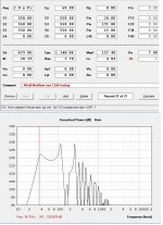
Matthew, the TS parameters I used (as I calculated off the spec sheet) are much different than yours. Here is what I get using "your box" with it's parameters as I understand them. The reason I didn't go any smaller in depth as it appears you chose is I limited myself to driver depth + 1 for venting/headroom because this assumes mounting it the way I've mounted my alpines previously, flipping it around and I could make it ~1 inch shallower all the way around (2 inches less total). After math I see that your box @ 550 sqcm correlates to a total depth of 15.5 inches, mighty nice for me, considering switching and then from mounting the driver.
<see image attached>
XRK:
I can't understand how our boxes simulate so different in different programs seeing as I checked your ts parameters and they seem fine... P.S. I'm not concerned about flat and would rather have that bump for low end "head room" assuming i'm not sacrificing too much 50-100 output.
Why does yours appear to be a 45 Hz spike when mine quite clearly is a 38 hz spike?
Looking at the script it looks like you may have simulated the 39 inch tall version (just going over some of the lengths now)? I grew the design by 3 inches to "properly" get the tune under 40...
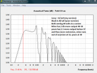
Forgot to mention, 81 volts would fry this voice coil right? I mean it's rated for 500 rms so maybe peaks of 1000 would be alright but rather bold to simulate that high...
68 is the highest I would go as that is 15 mm excursion at 45 hz according to hornresp in my version of the box.
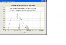
<see image attached>
XRK:
I can't understand how our boxes simulate so different in different programs seeing as I checked your ts parameters and they seem fine... P.S. I'm not concerned about flat and would rather have that bump for low end "head room" assuming i'm not sacrificing too much 50-100 output.
Why does yours appear to be a 45 Hz spike when mine quite clearly is a 38 hz spike?
Looking at the script it looks like you may have simulated the 39 inch tall version (just going over some of the lengths now)? I grew the design by 3 inches to "properly" get the tune under 40...
Forgot to mention, 81 volts would fry this voice coil right? I mean it's rated for 500 rms so maybe peaks of 1000 would be alright but rather bold to simulate that high...
68 is the highest I would go as that is 15 mm excursion at 45 hz according to hornresp in my version of the box.
Attachments
Last edited:
Matthew, the TS parameters I used (as I calculated off the spec sheet) are much different than yours. Here is what I get using "your box" with it's parameters as I understand them. The reason I didn't go any smaller in depth as it appears you chose is I limited myself to driver depth + 1 for venting/headroom because this assumes mounting it the way I've mounted my alpines previously, flipping it around and I could make it ~1 inch shallower all the way around (2 inches less total). After math I see that your box @ 550 sqcm correlates to a total depth of 15.5 inches, mighty nice for me, considering switching and then from mounting the driver.
<see image attached>
XRK:
I can't understand how our boxes simulate so different in different programs seeing as I checked your ts parameters and they seem fine... P.S. I'm not concerned about flat and would rather have that bump for low end "head room" assuming i'm not sacrificing too much 50-100 output.
Why does yours appear to be a 45 Hz spike when mine quite clearly is a 38 hz spike?
Looking at the script it looks like you may have simulated the 39 inch tall version (just going over some of the lengths now)? I grew the design by 3 inches to "properly" get the tune under 40...
Saba ,
Ok , you have a few things going on here, first be sure to click on the little red "TH" just below "Re" until it turns into "OD" ... This puts us into Offset Driver pipe mode instead of Tapped mode ...
I am just now loading the parameters for the 12D4 in HR (i was using the 12D2 before) ..... Upon entering the T/S figures i see that the motor strength in this driver is actually stronger ! which is a good thing
(assuming that the moving mass and suspension are exactly the same a lower QES indicates a stronger motor!) ... Another improvement is the increased QMS on this driver , thats a good thing too ! Now, my advice on the saddle shaped curves and "ringing" resonant peak at FB is that you have to keep in mind that Hornresponse always shows an exaggerated version of what you would get in real life when it comes to these peaks and saddles , however if that contour is bad enough in sim it actually will manifest itself in real life and then it is not really a good thing because it indicates that group delay is not as tight as it could be , cone control is also not as good as it could be and the bass reproduction will tend to sound less-than-natural and not very musical ...
If you notice i will always raise my LE in simulations (which often reduces the saddle shape of the response) and gives you a better idea of what the bass response will be in the real world , however this is just a "hack" and only just helps to approximate things (but its not perfect by any means) , when instead it would be great if David Mcbean could add a "lossy" option to his simulator in order to accomplish the same thing with more accuracy ....
If the saddle (also called "underdamped" response) does show up in real world measurements then some stuffing can be added at the beginning 25% to 33% of the pipe to straighten things out .....
In the end you really don't want a severely underdamped response because a lot of heavy EQ will reduce your headroom .... Keep in mind that if you have to EQ boost 50hz through 80hz by even 3db then you are asking for double the amount of power from your amplifier in that range ...... As a general rule shooting for a flat-ish response and using minimal to no EQ will always provide maximum headroom ..... Its really a shame that crummy room acoustics make us have to use EQ sometimes..
If you are someone who always tends to want to add a little bit of EQ around FB then making the response slightly underdamped might not hurt if it means that you don't have to apply any EQ ..
Last edited:
This is the 40.5 in tall version that you posted last. I have to go into the spreadsheet that GM gave link to to see if the T/S params are correct. I put everything in according to Alpine's data sheet but doubled the Re for DVC in serial. But I think other things need adjustment too. How did you get the T/S params for a DVC in series for HR?
One reason your HR may be different from mine is that I use the median pathlength for the distances between nodes. Meaning a path down the middle and I get 78 inch (198 cm) long path from closed end to the mouth. Your HR input above seems to have 226 cm total path. That corresponds to the difference in the knee point. I checked my geometry, it may be a tad off near the mouth as the channel goes from a 7.5 in width to a 10.25 in opening - but that is insignificant from fb standpoint (I just checked and no difference really). Akabak is extremely accurate at predicting the low bass knee point accurately given accurate dimensions matching what is built. I have many builds to prove this, and in many alignments (BR, DCR, TH, TP, PP-SL-BP, BLH, etc. all were within a few Hz). If you build it to the drawing, I would bet you my sim gets the knee point correct. With regards to max power, I adjust voltage to get xmax within limit, if the thermal power is too high, that is a different situation. However, the xmax is at a peak-to-peak, temporary point and the rms power is lower. RMS is 0.71 of peak (assuming sine wave music power) so I get 580 watts rms.
One reason your HR may be different from mine is that I use the median pathlength for the distances between nodes. Meaning a path down the middle and I get 78 inch (198 cm) long path from closed end to the mouth. Your HR input above seems to have 226 cm total path. That corresponds to the difference in the knee point. I checked my geometry, it may be a tad off near the mouth as the channel goes from a 7.5 in width to a 10.25 in opening - but that is insignificant from fb standpoint (I just checked and no difference really). Akabak is extremely accurate at predicting the low bass knee point accurately given accurate dimensions matching what is built. I have many builds to prove this, and in many alignments (BR, DCR, TH, TP, PP-SL-BP, BLH, etc. all were within a few Hz). If you build it to the drawing, I would bet you my sim gets the knee point correct. With regards to max power, I adjust voltage to get xmax within limit, if the thermal power is too high, that is a different situation. However, the xmax is at a peak-to-peak, temporary point and the rms power is lower. RMS is 0.71 of peak (assuming sine wave music power) so I get 580 watts rms.
Last edited:
Here is an excel spreadsheet of all the heights and depths I've simmed and their responses described as voltage handling, peak, trough, output freq's (you'll get the picture once you look at it).
https://docs.google.com/spreadsheets/d/16YG6SQjxL0XAKOEbCIdfA6TkRRLhPwjONP_GOzampZg/pubhtml
If anyone wants write access let me know and I'll share it with them.
https://docs.google.com/spreadsheets/d/16YG6SQjxL0XAKOEbCIdfA6TkRRLhPwjONP_GOzampZg/pubhtml
If anyone wants write access let me know and I'll share it with them.
This is the 40.5 in tall version that you posted last. I have to go into the spreadsheet that GM gave link to to see if the T/S params are correct. I put everything in according to Alpine's data sheet but doubled the Re for DVC in serial. But I think other things need adjustment too. How did you get the T/S params for a DVC in series for HR?
One reason your HR may be different from mine is that I use the median pathlength for the distances between nodes. Meaning a path down the middle and I get 78 inch (198 cm) long path from closed end to the mouth. Your HR input above seems to have 226 cm total path. That corresponds to the difference in the knee point. I checked my geometry, it may be a tad off near the mouth as the channel goes from a 7.5 in width to a 10.25 in opening - but that is insignificant from fb standpoint (I just checked and no difference really). Akabak is extremely accurate at predicting the low bass knee point accurately given accurate dimensions matching what is built. I have many builds to prove this, and in many alignments (BR, DCR, TH, TP, PP-SL-BP, BLH, etc. all were within a few Hz). If you build it to the drawing, I would bet you my sim gets the knee point correct. With regards to max power, I adjust voltage to get xmax within limit, if the thermal power is too high, that is a different situation. However, the xmax is at a peak-to-peak, temporary point and the rms power is lower. RMS is 0.71 of peak (assuming sine wave music power) so I get 580 watts rms.
Oh so the voltage spec on the sim is peak voltage? I'm an EE, you can talk geek to me
. I assumed the number on the picture was representative of rms.Saba ,
Ok , you have a few things going on here, first be sure to click on the little red "TH" just below "Re" until it turns into "OD" ... This puts us into Offset Driver pipe mode instead of Tapped mode ...
I am just now loading the parameters for the 12D4 in HR (i was using the 12D2 before) ..... Upon entering the T/S figures i see that the motor strength in this driver is actually stronger ! which is a good thing
Now, my advice on the saddle shaped curves and "ringing" resonant peak at FB is that you have to keep in mind that Hornresponse always shows an exaggerated version of what you would get in real life when it comes to these peaks and saddles , however if that contour is bad enough in sim it actually will manifest itself in real life and then it is not really a good thing because it indicates that group delay is not as tight as it could be , cone control is also not as good as it could be and the bass reproduction will tend to sound less-than-natural and not very musical ...
If you notice i will always raise my LE in simulations (which often reduces the saddle shape of the response) and gives you a better idea of what the bass response will be in the real world , however this is just a "hack" and only just helps to approximate things (but its not perfect by any means) , when instead it would be great if David Mcbean could add a "lossy" option to his simulator in order to accomplish the same thing with more accuracy ....
If the saddle (also called "underdamped" response) does show up in real world measurements then some stuffing can be added at the beginning 25% to 33% of the pipe to straighten things out .....
In the end you really don't want a severely underdamped response because a lot of heavy EQ will reduce your headroom .... Keep in mind that if you have to EQ boost 50hz through 80hz by even 3db then you are asking for double the amount of power from your amplifier in that range ...... As a general rule shooting for a flat-ish response and using minimal to no EQ will always provide maximum headroom ..... Its really a shame that crummy room acoustics make us have to use EQ sometimes..
If you are someone who always tends to want to add a little bit of EQ around FB then making the response slightly underdamped might not hurt if it means that you don't have to apply any EQ ..
Thanks for the insight, I didn't take into account group delay and usually I just EQ down the peak at FB and then I can take a slightly higher signal at that frequency (headroom). I'm well aware of what underdamped response looks like
control systems is a required class for us, and they cover it in several EE classes.Ignore my entire excel spreadsheet until I update it, simmed everything with TH style oops.
OOH, Loving the Nd setting, haha, so a pair of sws 12's in a 19.25 deep 13 wide 58 long (dual loaded single cabinet) is looking usable down to 27 Hz!!! Albeit it's rolled off a bit by then but the excursion is kept down until 26 Hz. 126-127 db 50-100 Hz with a nice slow taper all the way down. (124 at 35 hz).
Also, my new simulation with the 15 inch version looks mighty appealing at 126 dB of output 40-50 Hz
Also, my new simulation with the 15 inch version looks mighty appealing at 126 dB of output 40-50 Hz
Last edited:
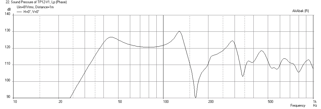
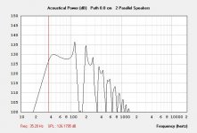
Here is the Alpine SWS-12D4 in both a OD-QWP format and also COMPOUND OD-QWP sort of alignment , both with raised LE for more realism in sim purposes .... 72..5 volts ... Just barely touches 15mm ..
I like this driver , good results here
Absolutely competitive with two of the E series 10S4s ..
Saba , to answer your question from earlier a compound alignment just means more resonators ... So in this we have a resonator on the front of the cone as well as the back ... The one on the front can be very small and is just used to fill in the gap between the 3rd and 5th harmonic but appears to add a little bit of extra gain throughout the midbass range and even a smidgeon down low .... It also seems to add some damping well below the FB on the smaller resonator, at least that is what it shows in sim ..
Also , i wanted to make sure that you know (because i think you will appreciate this) the woofer is mounted on the outside of the box with the magnet inside ( the driver is not hidden inside of chambers like the tapped alignments we were working on) so there are no issues with ease of access , and no need for removable panels !
Attachments
Last edited:
Do you suppose GM will notice the message in the above sketches?
Could you draw in paint a very rough sketch of this design? looks quite awesome. Here is my counter design
My design is basically your tapped pipe but 42 tall instead of 46, allows slightly higher voltage (this touches 15 mm at 75 volts). Slightly higher tune but only down 1 dB from yours at 35 when driven in pairs. For Clubs/installs I'll probably go with the larger dual loaded cabs as they have usable extension sub 30 which in some cases can be nice (and they don't care as much that they are really long)Attachments
Comparison, 46 vs 42 tall, everything else constant (69 volts corner loaded, cross section). I'll take either .
Semi-final decision is your 46 tall version, with a 32 hz HP 2nd order and 8th order lp at 98. Makes it razor flat and <20 ms group delay from filters!
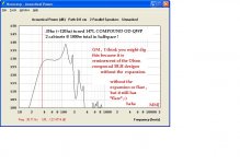
Now I need to come to an agreement with XRK as to what panel dimensions will accurately represent the sim. I'll be posting a side view with lines drawn to show how I measured the segments, hopefully that will shed light on any discrepancies.
.Semi-final decision is your 46 tall version, with a 32 hz HP 2nd order and 8th order lp at 98. Makes it razor flat and <20 ms group delay from filters!
Now I need to come to an agreement with XRK as to what panel dimensions will accurately represent the sim. I'll be posting a side view with lines drawn to show how I measured the segments, hopefully that will shed light on any discrepancies.
Attachments
Last edited:
Think you made a typo, sws 12d4 has the 15 mm xmax. Says swe12d4, which doesn't exist
Thanks , Im glad you saw that , i was able to fix it before the edit time ran out
Comparison, 46 vs 42 tall, everything else constant (69 volts corner loaded, cross section). I'll take either
Semi-final decision is your 46 tall version, with a 32 hz HP 2nd order and 8th order lp at 98. Makes it razor flat and <20 ms group delay from filters!
Now I need to come to an agreement with XRK as to what panel dimensions will accurately represent the sim. I'll be posting a side view with lines drawn to show how I measured the segments, hopefully that will shed light on any discrepancies.
With a little creative strategic mass loading (the "C" word) we could being the height down below 39 inches , 36 possibly
Thanks , Im glad you saw that , i was able to fix it before the edit time ran out
121 dB to 35 Hz is pretty darn good for a single 12.
15.25 deep 14.5 wide 46 tall (tentative) it should come in at 5.88 cu. ft. which means 3.5 of these per T60 (120 dB at 30 Hz 124 at 50 Hz 21.8 cu ft folded horn)
->
(although it's cheating because the power consumed would be 4 to 1 or more)
for the same volume you would be looking at 8 dB more output to 30 Hz!
With a little creative strategic mass loading (the "C" word) we could being the height down below 39 inches , 36 possibly
As long as the simulated "constriction" velocity is below the flare-it threshold for compression, I'm open to considerations. However, with no ports I could build the whole thing in 3 days most likely, would take 4-5 with ports. However, some places couldn't fit the extra 6+ inches...
- Home
- Loudspeakers
- Subwoofers
- New sub design? Constricted Transflex, simple build (series tuned 6th order)