
https://www.diyaudio.com/community/threads/tda1541-a.393705/#post-7213897I need another TDA1541A dac chip. Anyone has one to sell in EU at a reasonable price?
Update after burn-in:
Fantastic music machine! Best DAC I tried on my setup!


Many many thanks to Papa & ZM
Fantastic music machine! Best DAC I tried on my setup!
Many many thanks to Papa & ZM

Because of your huge help and superb PCB layout!
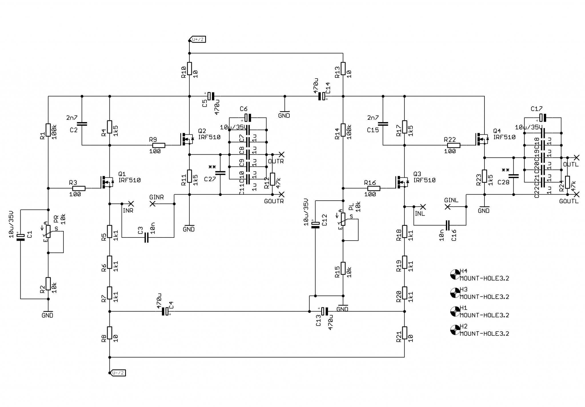
Wich are safe limits for voltage gain settings (R4 values)?
Wich are safe limits for voltage gain settings (R4 values)?
if you increase R4 from 1K5 to 1K8, it'll give you 1.8/1.5 increase of output swing
in any case, don't go above 2K
change R11 downward in value by same ratio; so, if going with R4 to 1K8, change R11 to 1K2 (nearest standard value); that for keeping output source follower current on same level
be sure to check/reset DC level at input node after any change
in any case, don't go above 2K
change R11 downward in value by same ratio; so, if going with R4 to 1K8, change R11 to 1K2 (nearest standard value); that for keeping output source follower current on same level
be sure to check/reset DC level at input node after any change
Dear friends
I was using a diy 2X TDA1541A S1 with the D1 i/v, from 2008 until last year. It was direct connected to my diy CD pro2 player with the i2s port.
The sound was great and much better than any other DAC I had test. Last year I finished a DAC (starting from 2014) using 4X TDA1541A, with 4x coax s/pdif , 2x i2s and a USB input. The only change on D1 was to put parallel, to R4 and C2 , a 1k5 and 2.7nF because of the four dacs. The sound is much better with higher levels of music especially when I use the B1 as a preamp.
I also use PCBs with the TDA1387 instead of 1541a, but there is not comparison, because 1541a is much more natural. I think that only the bass of 1387 is a little better with more presence. And a few pics of it. The enclosure was from a previοus active x/over.
With kind regards
Kostas A. Vazakas
Greece
Attachments


The only change was made to reduce the gain in the D1, because of the four TDA1541A.
if you increase R4 from 1K5 to 1K8, it'll give you 1.8/1.5 increase of output swing
in any case, don't go above 2K
change R11 downward in value by same ratio; so, if going with R4 to 1K8, change R11 to 1K2 (nearest standard value); that for keeping output source follower current on same level
be sure to check/reset DC level at input node after any change
I assume that to lower the gain I would need to decrease R4 and increase R11 by the same ratio. Is that correct? How could I calculate R4 and R11 values if for example I want to decrease gain 2x?
Hi peppennino
Congrats on your tda1541 project!. It looks like it came out great!
I hadn’t come across this thread before.
I’ve been like a squirrel on a triple espresso lately…all over the place with my projects.
This past week my tda1541 project got on my nerves when wifey wanted to crank some dance music…DAC didn’t have enough cojones.
I’m using a pair of Ryan’s D3 boards running parallel tda1541 fed by his I2S to Simultaneous board with signals and whatnot handled by one of IanCanada’s original SPDIF and Fifo setups.
When I got it up and running at the end if 2020 I had difficulty wrapping my head around i/v stage options.
I ended up just plopping in some 110 Ohm mk132 i/v resistors and started playing it.
It’s OK for the most part, but I’d like to sort it out with better gain on the output.
I have an old SEN i/v board I found in the swap meet. I could try and populate it…but not excited about using a battery supply and don’t know how else I could do the floating supply.
Also came across some DAC transformers I grabbed prematurely I think.
It looks like I’d have to switch my setup over to differential and I think they will produce a high output impedance as they are dual primary and wound to 0.5 + 0.5:22.
They are set up with an 11k i/v resistor on the secondary which is supposed to reflect a 22 Ohm load on the chip output. I’m a bit confused about how low the i/v resistor can or should go.
I’m wondering how you sorted out the i/v resistor value in your setup?
Also I’m wondering if you have any extra copies of the D1 i/v stage boards you had made up and if it might be possible for me to use it in my setup?
Attachments

Hi BenAs you said, the TDA1541A actually wants see a low impedance load for best performance.
The data sheet (page 7) says, "To ensure no performance losses, permitted output voltage compliance is ±25 mV maximum."
The current output of the chip is +/-2mA, with an offset of -2mA.
So for +/-25mV, maximum, the chip wants to see about 12 Ohm maximum. I'm sure that is why peppennino is interested in the D1's input impedance. 🙂
But then I load my dac with about 70R IV resistor and enjoy its sound. diyAudio member ecdesigns (John Brown), who has done a lot of work with the TDA1541A, has suggested that up to 150R may be used for IV.
ecdesigns IV resistor
But the D1 circuit is cool. The input mosfet is a current buffer. 🙂
I may try it but use a lower value for R4 since I don't need 3Vp output.
Just read this again.
I’m wondering…how low I can go with the i/v resistor on the tda1541?
Ryan had suggested to me to leave the current injection in place on the D3 boards and first try a i/v resistor on the primary of the transformers.
Supposedly the transformers I have will multiply a primary i/v resistor’s value by 484 times.
A 12 Ohm resistor would get me down to about 5.8k.
Still a bit high for my DCB1 with 20k pots.
My tube pre is at about 47k input impedance.
No idea what my Iron Pumpkin with Turtle will have for input impedance.
I had gone as low as 10 or 12 Ohms when I used to have a tube stage after the IV resistor. That was many years ago.
Yes you can. I wrote a build guide for the D3 board. Pm me and I will send it to you.Thanks, Ben. It looks fantastic but I cannot solder a two-sided SMD board since I don't have the means and the skills
chromenuts, I just had a look at your numbers. If your transformer is 0.5+0.5:22 , and if the primary is connected in series, it is 1:22. The impedance ratio is 1:22x22, or 1:484. So that is where 484 comes from.
Now if you have 12 Ohm at the primary, your output will be quite low, even after the transformer 22X. The TDA1541A current output is +/-2mA (after offset correction). With 12R IV resistor, voltage output is 0.024Vp or 0.017Vrms. After the transformer at 22X, it would be 0.374Vrms but that is before insertion loss (perhaps 20%). So at the transformer output it could be 0.30Vrms. Now with your 110 Ohm IV resistor, the output would be 0.002A x 110R x 0.707 = 0.156Vrms, so approximately half of the transformer output.
I was looking at some information on the web re:IV transformers and it seems that the IV resistor is usually placed across the transformer secondary. For the TDA1541A to see 12R, the resistor across the secondary would be 12R x 484 = 5.8K.
The transformer does present a very high output impedance. However I think the Iron Pumpkin has an input buffer so the high impedance may not be an issue.
- Home
- Amplifiers
- Pass Labs
- NOS TDA1541 + D1 I/V & output stage