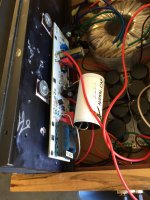
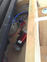
Very nice - where are the chokes?
Looks like you can see one to the back left of the power toroid in the first picture.
from Amazon site
https://www.amazon.com/dp/B0002ZPR10/ref=sr_ph_1?ie=UTF8&qid=1465578490&sr=sr-1&keywords=erse
Best
Bob
https://www.amazon.com/dp/B0002ZPR10/ref=sr_ph_1?ie=UTF8&qid=1465578490&sr=sr-1&keywords=erse
Best
Bob
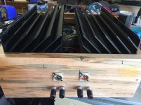
Great, thanks! These appear a bit less bulky than the ones I used. I'll post pics of my build when I finish it, hopefully next week. Also - where did you get those great heat sinks?
I've had those heat sinks for 25 years

Nice !
Anybody able to help?
I built the M2 using Teabags board but made an error on one and blew a few components. I put the optocoupler in the wrong way round and set fire to R12, R13 and R14. I have spare optocouplers and resistors but after replacing them R13 blew again.
What other components need checking and can I do this with basic equipment (I have a decent multimeter and a transistor checker from ebay)?
Last edited:
I said - right from the xformer
ref to schm in #1 , I would replace Q1 ,Q2,Q5,Q6,Q7,D1,D2,D3,R6,R7,R8,R9,R10,R11,R12,R13,R14,P1
now seriously - I would check them and find which part is kaput , but you must suffer , to drew reminder for future , to triple check before powering up
besides that , I can't know precisely what else you done .....
Last edited:
My first costly mistake, hopefully my last....
I'm repeating that every other day ........

- Home
- Amplifiers
- Pass Labs
- Official M2 schematic