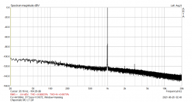
Old designs of decades ago had RF filtering. Today the aether is chockfull of RF and even modern designs by known designers lack RF filtering (add power on/off muting and DC protection to that). Modern silicon is way more wideband too. Some designs are proudly presented with plots going in MHz range…
Contradictory.
This is very true. I was able to produce some extremely loud pops by placing my phone directly on top of a commercial phono preamp.
The LM4562 is an exception, but otherwise it are the fast op-amps that JRA has trouble with:
Misbehaving:
OPA1656, gain-bandwidth product 53 MHz
LME49990, 110 MHz
OPA1612, 40 MHz
Behaving well:
OPA2604, 20 MHz
OPA627, 16 MHz
OPA2107, 4.5 MHz
LM4562, 55 MHz
OPA2134, 8 MHz
A 1 metre cable with polyethylene dielectric has its first resonance at 50 MHz, a 1.5 metre cable at 33.3 MHz. This doesn't prove my hypothesis, of course, but the trends match: when the op-amp still has loop gain around the quarter-wave resonance of the cable, it usually misbehaves in JRA's set-up.
Most important with high speed opamps is decoupling the power lines as close as possible to the op-amp.
In your case I see none, a serious omission leaving the door wide open for oscillations.
Don’t blame the 1656, it’s an excellent amp, just like the 1612 etc, etc.
Hans.
Hans, take another look at photo #4 of post #571. Look for an axial lead capacitor with yellow body, mounted diagonally.
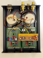
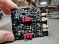
Its good to also have decoupling caps between a chip's power pins and the zero line. That cross rails one wasn't as effective in some breadboard experiments I have done with various chips. I have used the OPA1656 as output stage X10 and DC servo utilizing general purpose matrix boards construction style like JRA too.
Input is balanced impedance Jensen X10 step up to an Analog Devices 1nVrtHz instrumentation amplifier DIF input chip X121. X1210 total after passive RIAA loss. No cross rails decoupling underneath, just those two vertical and horizontal red 0.1uF MKT Wima visible near both the INA and the OPA.
Input is balanced impedance Jensen X10 step up to an Analog Devices 1nVrtHz instrumentation amplifier DIF input chip X121. X1210 total after passive RIAA loss. No cross rails decoupling underneath, just those two vertical and horizontal red 0.1uF MKT Wima visible near both the INA and the OPA.
Attachments
Assuming you have a cartridge that requires a very low load capacitance (does it?), you could try something like 82 ohm in series with 47 pF across the input. You could also connect it as an RC low-pass filter between the input and the op-amp, that will give some extra rejection of picked up RF signals at the expense of a very small increase of the noise.
Yes, the pdf of the schemo has a list of specs for my MM cart. Audio Technica recommends 200-300pf all inclusive. My interconnect between the TT's output RCAs and the RIAA pre is 3ft and 17pF/ft. The TT's internal wiring creates another 144pF so the (measured) cart-to-pre box total =~195pF. Users who can change loading and measure the response of this cart say "lower the better" ... "keep it at or under 200pF" such that the resonant LCR bump in the treble is less and occurs/begins at a higher freq. Thus is why you don't see any fixed C across the 47K.
As far as the voltage reading I get across the 47K, that's done with no input. I'm just checking to be sorta sure of what I got from China and/or whether maybe the DIP8 assembly needs further cleaning with 91% IPA. I check Vout as well looking for anything weirdly out.
Stay tuned for some revealing new pics.
The LM4562 is an exception, but otherwise it are the fast op-amps that JRA has trouble with:
Misbehaving:
OPA1656, gain-bandwidth product 53 MHz
LME49990, 110 MHz
OPA1612, 40 MHz
Behaving well:
OPA2604, 20 MHz
OPA627, 16 MHz
OPA2107, 4.5 MHz
LM4562, 55 MHz
OPA2134, 8 MHz
A 1 metre cable with polyethylene dielectric has its first resonance at 50 MHz, a 1.5 metre cable at 33.3 MHz. This doesn't prove my hypothesis, of course, but the trends match: when the op-amp still has loop gain around the quarter-wave resonance of the cable, it usually misbehaves in JRA's set-up.
Yep, I went looking for common attributes of the "excitable boys" and thought GBP, slew-rate and AVol might hold some clues and was nodding my head, yes, could be that and an amateurish layout.
I must get today's scope shots out there. They may answer many questions.
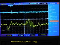
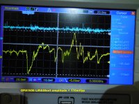
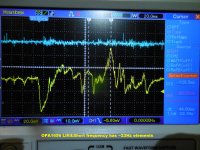
The way I did this THUMP test was to Blue-trace the cart’s right chan at the RIAA pre’s input RCA connector and to Yellow-trace the pre’s RCA connector output (hooked to the main pre’s Aux Line Input as usual).
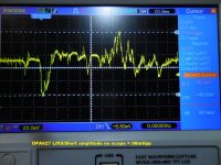
In order to exercise the TT’s mute switch I used its “Lift/Cue” function wherein a button press lifts the arm straight up off the rest and stops. Along the way it shorts the cart’s outputs - aka here as “Lift&Short”.
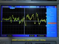
A second press has the arm lower back down to the rest and along the way the cart outputs are un-shorted - aka here as “Lower&Open”.
With this scope setup I got the attached display shots. Compare the docile OPA627 to the speaker-eater OPA1656. Don’t look all that crazy different do they? Note that the Blue-trace cart output gives no indication of a smoking-gun input disturbance. 10mV/div is as low as my scope goes.
In order to exercise the TT’s mute switch I used its “Lift/Cue” function wherein a button press lifts the arm straight up off the rest and stops. Along the way it shorts the cart’s outputs - aka here as “Lift&Short”.
A second press has the arm lower back down to the rest and along the way the cart outputs are un-shorted - aka here as “Lower&Open”.
With this scope setup I got the attached display shots. Compare the docile OPA627 to the speaker-eater OPA1656. Don’t look all that crazy different do they? Note that the Blue-trace cart output gives no indication of a smoking-gun input disturbance. 10mV/div is as low as my scope goes.
Attachments
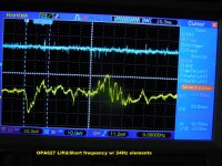
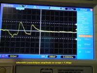
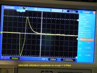
Now, I remembered how just the presence a scope probe could cause circuit trouble or cause circuit trouble to vanish. For this round of pics I removed the Blue probe + the solid 1-male => 2-female adapter used to allow tapping into the RCA input and plugged the right channel TT input cable straight in as per usual.
Hint = no more scope probe impedance across the 47K R.
These shots show both the Lowering and Lifting RIAA output results for both op amps. Seems that some posters here are on the right track. I have no endpoint pF at the op amp's + input or RC filter. My 195pF "load" for the cart is distributed all along the signal path.
Attachments
Its good to also have decoupling caps between a chip's power pins and the zero line. That cross rails one wasn't as effective in some breadboard experiments I have done with various chips. I have used the OPA1656 as output stage X10 and DC servo utilizing general purpose matrix boards construction style like JRA too.
Input is balanced impedance Jensen X10 step up to an Analog Devices 1nVrtHz instrumentation amplifier DIF input chip X121. X1210 total after passive RIAA loss. No cross rails decoupling underneath, just those two vertical and horizontal red 0.1uF MKT Wima visible near both the INA and the OPA.
Very clean looking layout. Love to see the bottom-side
") The small box type Wimas are very popular. For the main RIAA EQ caps did you find them in 1% or hand-select? I assume you used 0.1% Rs. What are the big cans, btw? Have you tried your RIAA box with a mute switch TT? I'm just real curious.
The small box type Wimas are very popular. For the main RIAA EQ caps did you find them in 1% or hand-select? I assume you used 0.1% Rs. What are the big cans, btw? Have you tried your RIAA box with a mute switch TT? I'm just real curious.I did use 0.1uF X7Rs at pin 4 and 8 and between 4 and 8.
Hi, have you got both 47K input termination resistors on the board? It's not clear from the pics.
Also does your TT short out the cartridge or ground it to an internal earth? If its the later there may be a small potential on that TT earth point. You could try adding a 1uF polyester capacitor to the inputs, see if that clears it.
Also does your TT short out the cartridge or ground it to an internal earth? If its the later there may be a small potential on that TT earth point. You could try adding a 1uF polyester capacitor to the inputs, see if that clears it.
Yes re 47K input load. See my original post PDF attachments for basic schematic, page 56.
I believe that the mute switch simply shorts the cart's output leads together w/o involving any kind of metallic Gnd or Earth b/c there is none. The cart outputs are floating and the TT has the traditional Gnd wire connecting to the receiving preamp's signal Gnd which I thought then tethers the TT's metal bits to system signal Gnd. With that written I just don't remember what that Gnd wire connects to...
I believe that the mute switch simply shorts the cart's output leads together w/o involving any kind of metallic Gnd or Earth b/c there is none. The cart outputs are floating and the TT has the traditional Gnd wire connecting to the receiving preamp's signal Gnd which I thought then tethers the TT's metal bits to system signal Gnd. With that written I just don't remember what that Gnd wire connects to...
Last edited:
Very clean looking layout. Love to see the bottom-side
I did use 0.1uF X7Rs at pin 4 and 8 and between 4 and 8.
The blue resistors were low ppm, also better than 1% maybe. Not sure because I stuffed those boards almost three years ago. The gray and blue ERO MKP rectangular caps 1%. The blue I hand matched it to the 5% Wima MKP red next to it and to the blue balloon styrene 5%. All three in parallel to a total HF pole cap value goal. I don't have a mute switch TT.
Three friends built a surface mount PCB version with a regs section too that I authored with one of them. Five were ever printed. They had a layout bug to bodge as well. I kept the matrix boards prototype. Was measuring right so I saw no reason to remake it in SMT.
Attachments
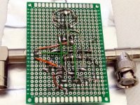
Yes, that back-side is looking appropriately DIY ratty As I wrote in my original post page 56 I chose to go old-school with polystyrene b/c of their vaulted reputation and found them surplus in just about any odd value you can imagine. But they run large-bodied and what you want may not be in the smaller 25 or 33V body size so one settles for the 60 or 160V body which then expands the layout - requires longer leads and jumper paths back to the op amp, etc. I guess nH add up.
Still am curious about the two large cans in you original pic of the RIAA box..?
As I wrote in my original post page 56 I chose to go old-school with polystyrene b/c of their vaulted reputation and found them surplus in just about any odd value you can imagine. But they run large-bodied and what you want may not be in the smaller 25 or 33V body size so one settles for the 60 or 160V body which then expands the layout - requires longer leads and jumper paths back to the op amp, etc. I guess nH add up.Still am curious about the two large cans in you original pic of the RIAA box..?
- Home
- Source & Line
- Analogue Source
- OPA1656 Phono Preamp: Split from OPA1656 thread