Thank you.Good job! Those Ccb capacitors (470pF or your 1nF, this depends on output devices speed) are mandatory, in the real circuit.
Yes, for Siziklai pair they are mandatory. In test build are used non liner X7R ceramic capacitors. I will change that to C0G.
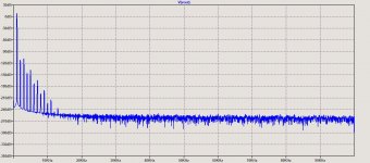
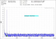
I have plenty of old measurements, like this one 4W/8ohm (Y axis dBVrms is wrong designation, it is not calibrated). The buffer keeps only low order harmonics at lower power like this. Focusrite in your plots created the high orders.Distortion is very low
Attachments
Adason opened quest for a simple superb sounding buffer. That has set me on the right track to what my summer amplifier should be. Thanks again adason.I use similar buffer in my preamp to drive headphones.
I doubt that any average forum member can put together amplifier that was not built and measured before, so I’ve put together something that should work good with low supply voltages and dissipation for a specific purpose.
I encourage anyone having “beefy” wide bandwidth preamplifier like Salas DCG3, ACP+ or Noir HP amp, to connect loudspeakers at preamplifier output and listen. Level would be just enough for enjoyable listening but it may surprise you what is present in the soundstage.
So, ATM my road leads to good buffer supplementing preamplifier with enough output current.
CCS do not help much in the real circuit. Again, do not believe simulations to much. The models are incomplete to describe real parts completely. With the class A buffer I have shown, opamp front end and no gnfb I get <0.01% distortion at 20W. If the gnfb loop is closed, it is below 0.001%. Learn and grow guys, and go and build prototypes. Never stick with the simulation only, with simulation you have the first little step but in fact almost nothing.
And I repeat that I believe only in measured data. Simulation is helpful.Again, do not believe simulations to much.
BTW there was one extreme case on this forum, a guy trying to prove his point with hundredths of flawed simulations flood. Ruined several threads.
??Learn and grow guys, and go and build prototypes.
I’ve built and measured prototype not another simulation.
I’m not young enough to grow but can learn. 🤣
Last edited:
Isn't that what we are doing here?CCS do not help much in the real circuit. Again, do not believe simulations to much. The models are incomplete to describe real parts completely. With the class A buffer I have shown, opamp front end and no gnfb I get <0.01% distortion at 20W. If the gnfb loop is closed, it is below 0.001%. Learn and grow guys, and go and build prototypes. Never stick with the simulation only, with simulation you have the first little step but in fact almost nothing.
I do not simulate, never did. Well, maybe when i was a kid and did not feel like going to school.
Neither do i grow anymore, well maybe morning wood.
Question: i can set my buffer at any current. I have fixed power supply +/- 22 vdc. How do i calculate when the buffer leaves classA and becomes classAB? Say for currents 5mA, 50mA, 100mA and 500mA.
Yes of course, final step is to build and enjoy.Depends, circuit by circuit. However, it is never a final step. I think you know.
During my DIY life I have buit many electronic components, but mostly not my design. When Spice software start to be affortable or even free, I started to design and build (only 🙂) my own staff with great satisfaction. I like LTspice a lot.
You will not ask that question if you start to simulate.😉Isn't that what we are doing here?
I do not simulate, never did. Well, maybe when i was a kid and did not feel like going to school.
Neither do i grow anymore, well maybe morning wood.
Question: i can set my buffer at any current. I have fixed power supply +/- 22 vdc. How do i calculate when the buffer leaves classA and becomes classAB? Say for currents 5mA, 50mA, 100mA and 500mA.
Isn't that what we are doing here?
How do i calculate when the buffer leaves classA and becomes classAB? Say for currents 5mA, 50mA, 100mA and 500mA.
A class operation ends when peak output current reaches double value of bias. For 0.5 A Iq A class operation will end at 1A peak. RMS value is peak value/1.41 = 0.71 A rms.
Power to the loudspeaker is square of current * resistance. That gives 4 W rms power at 8 Ω loudspeaker. For a 4 Ω loudspeaker, A class operation will end at 2 W rms.
Yes. And then it switches to class AB with sudden appearance of high order harmonics. So idle current of 1.5A is the least usable value. A lot of heat, then. Too much heat - big good casework with large heatsinks is required. It is a good training, however absolutely impractical. If you want to design a good amp with enough power, go another way. This is just a training for fun, nothing more.
Why so effing patronizing. Was just asking.
I tripled the outputs in my other buffer you know. Not looking for much power, if you read the first post.
I tripled the outputs in my other buffer you know. Not looking for much power, if you read the first post.
If you bought a few hundred parts before they went EOL,
2SC5171 / 2SA1930
You can find a few for diy in onkyo receiver scrap. These have beta of 180-ish (npn) and 250-ish (pnp).
Btw the outputs I've got with these are A1962 and C5242, beta around 130.
@Mark Johnson
@rayma
Attachments
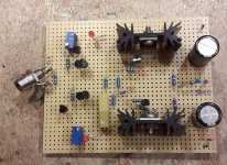
It's similar to one showed here, just with output mosfets, and it's just for headphones not loudspeakers.No worries. You posted measurements of your buffer, but not a schmatics, is it a secret?
My return to child’s play, leaving real amplifiers design to grown men. 😆If you want to design a good amp with enough power, go another way. This is just a training for fun, nothing more.
Buffer was harassed for stability and performance, followed with some tweaking, schematics changes and more measurements. I’m now satisfied with overall performance and stability.
Goal of this whole exercise was to check if simple low dissipation and output power pure A class amplifier with no GNFB, which measures and sounds excellent, is feasible. Results say that it is. Simple buffer can provide an excellent performance.
Setting an example, what can be achieved in the “department of simple where less is more”, Nelson Pass is designing extraordinary amplifiers with just 3 – 4 semiconductors and several resistors, so we should not judge amplifiers based on parts count.
Measured data:
Power bandwidth (-3 dB) at 1W/8Ω - 820 kHz.
Power bandwidth (-3 dB) at 6W/8Ω - 380 kHz.
Amplifier’s PSRR - 76 dB (17 mV rails ripple measures as 2.45 uV at output).
Output noise of this ikebana style build - 53 uV (20Hz – 22 kHz).
Slew rate - 100 V/us (200 ns for voltage going from -10V to +10V) at 8Ω load.
Output impedance – 0.073 Ω.
Distortion, as seen on previous posted measurements is less than 0.002% at 1W and remains fairly low at high levels. Here is attached measurement at 7 Vrms output, what is max. output of signal generator. At that level signal generator is declared to have 0.02% distortion. I actually measured signal generator output distortion as 0.016%. So, amplifier distortion is 0.012%. Harmonics distribution is from the generator, not from the amplifier.
Miscellaneous
With component changes, H2 harmonic phase is now perfect negative (-90°). Visitors of Pass Labs forum section know what this is about.
There is no power on/off thump or any power on/off sound.
Capacitive load doesn’t affect stability. Tested up to 1 uF.
It would be really a child’s play to add input opamp for gain or to include buffer stage in the opamp NFB loop for a 0.0000x distortion, but this is not the goal at this moment.
Listening
Buffer purpose is to serve as impedance converter between signal source and loudspeakers, adding or removing as little as possible from the source signal or being completely transparent while providing enough output current.
For comparison was used Salas DCG3 preamplifier, single ended class A capable of driving directly efficient loudspeakers to moderate sound level. Switching loudspeakers drive between preamplifier or preamplifier + buffer, provided matched level and realistic differences comparison.
I have very good sound reproduction completely detached from the loudspeakers, meaning that you don’t perceive sound coming from the loudspeakers at all, but from the soundstage behind them, with lot of details and nuances. Loudspeakers simply don’t exist and there is so strong impression of artists performing right there in front of me, that I’m often compelled to look up straight to see them better. Soundstage goes beyond LR loudspeakers positions and can be very deep, depending on recording, with firm positions for instruments and artists.
After several days of listening to various known tracks, I can say that buffer performs extremely well. Not a single bit of described good performance has changed, while much higher sound levels can be obtained. I count this as a great success, especially as simple common PS was used for both channels.
However, I’m aware that equally good result can be obtained with many other existing designs.
If I don’t stumble on better idea for low power solution, this buffer may get proper build as a complete amplifier.
- Home
- Amplifiers
- Solid State
- Output BJTs for buffer


