The 10 ohm spec. established by the Levinson JC-1, back in 1973 was established to properly amplify the Ortofon 50uV cartridge. When, soon after its introduction, Supex, FR came out with their 100uV output, and even Denon started selling their MC phono cartridges in the USA, the 10 equivalent noise spec still held well. When the Vendetta came out 8 years later, phono cartridges were gradually increasing in output, but a few Ortofons were still low in output, and some phono cartridges are still this low in output, today.
For most here, it does not matter, but some audiophiles want this range of low noise reproduction. In 1981, when I first made the prototype of the Vendetta, I only achieved about 20 ohms of noise, so I went on to parallel devices and made other changes, in order to reach 10 ohms of equivalent noise. This was made fairly easy with 2SK146V's and 2SJ72V's that were affordable and already matched in like pairs. The only matching requirement was the Idss of the N channels and the P channels. This was fairly easy, AND necessary.
Over the years, it has been harder and more expensive to make Vendetta like designs, but nobody wants to make a 'statement' product that is far off from what the Vendetta achieved 25 years ago, so we struggle on, and it is not easy, even with tens of thousands of devices, available to us.
We can sometimes get noisy devices, orphan devices (way out of range), and sometimes just no specific device in a given range is available.
This is why I tend to discourage people from taking on a Vendetta like design, lightly.
Can 1 nanovolt be OK? OF COURSE! For most MC phono cartridges, and the Parasound JC-3 is in this range, in fact it is even slightly noisier.
So go for it.
Well-stated, John.
BTW, if I'm not mistaken, the $20+k Boulder preamp is specified as having about 190 nV equivalent input noise, and has been described as dead quiet by a Stereophile reviewer. If we assume that 190nV spec by Boulder is for a bandwidth of 20 kHz, weighted flat since it is specified as input-referred, that would seem to come out to 1.35 nV/rt Hz. I freely admit that I may be wrong in interpreting the Boulder spec, however.
Cheers,
Bob
John,
Simple. The datasheet show the K147 and J72 Ein vs Id flattens out at 0.7nV/Hz regardless if Id.
With 4pcs the best case Ein will be 6dB lower, so 0.35nV|/Hz. However the resistor combo in the source lines as shown in the schematics others posted come back to 2 Ohm, or 0.18nV.
However I forgot to add up the noise sumsquared (I was distracted), so you are right, the noise is lower than 0.53nV|/Hz I came up with, in fact spot on 0.4nV...
The difference between the two numbers is less than 3dB.
So sorry, the wetware glitched. Need more beer I guess.
Ciao T
ThorstenL, please show me your calculations. Mine are different.
Simple. The datasheet show the K147 and J72 Ein vs Id flattens out at 0.7nV/Hz regardless if Id.
With 4pcs the best case Ein will be 6dB lower, so 0.35nV|/Hz. However the resistor combo in the source lines as shown in the schematics others posted come back to 2 Ohm, or 0.18nV.
However I forgot to add up the noise sumsquared (I was distracted), so you are right, the noise is lower than 0.53nV|/Hz I came up with, in fact spot on 0.4nV...
The difference between the two numbers is less than 3dB.
So sorry, the wetware glitched. Need more beer I guess.
Ciao T
Thanks ThorstenL for being so forthright. I got the same results. I am paralleling 4 total devices running at about 12 ma each. I, unfortunately need the resistor combo for bias and distortion balance, BUT in future, I might reduce its contribution to 1 ohm or so, just for 'bragging rights'. Syn08 got away with it, why not?
Hi,
Agreed.
Disagreed, it is why I opt for passive. Different strokes for different blokes.
I find it very hard to remove the unpleasant "mechanical" signature from any looped feedback based regulator.
A 3,300uF Cap is 24 Ohm at 20Hz, so in terms of noise from resistors not shunted it should give around 0.6nV|/Hz at 20Hz and less as the frequency rises. With maybe 100dB+ noise suppression the 3uV from the 317 will be completely killed, also any hum not regulated out.
I guess we can even relax the filtering, strictly on noise considerations, but I find it takes quite heavy handed passive filtering to get rid of feedback regulator sound.
With a single ended J-Fet stage and 150 Ohm load this boosts 20Hz by 1dB, the 3dB Point is 3Hz. Using a 2.2uF output coupling cap and an extra 47K resistor to parallel to the input impedance of the MM Stage we are back at flat...
All easily manageable and quite reliable in application.
This is not to say that regulators cannot be made to sound good, it's just too hard work for my taste. Pass the stout!
I have used CCS fed Shunts often (all sorts), if I can I prefer passive to them, personally speaking. Sadly feedback free shunts are not an option.
It is possible to use AC only CCS (electronic choke) and feed-forward based noise/impedance correction, in shunt, but again, the execution is non-trivial.
Don't get me wrong, your Shunt Reg is not bad, neither is the late Allen Wright's, but I tend to use other stuff now. If I had to use a shunt reg, something derived from yours would be well up the list.
Ciao T
Its not only about noise IMHO. Its the Zo of a PSU and its shape which is very important too.
Agreed.
That is why I opt for super shunt regulators.
Disagreed, it is why I opt for passive. Different strokes for different blokes.
I find it very hard to remove the unpleasant "mechanical" signature from any looped feedback based regulator.
A 3,300uF Cap is 24 Ohm at 20Hz, so in terms of noise from resistors not shunted it should give around 0.6nV|/Hz at 20Hz and less as the frequency rises. With maybe 100dB+ noise suppression the 3uV from the 317 will be completely killed, also any hum not regulated out.
I guess we can even relax the filtering, strictly on noise considerations, but I find it takes quite heavy handed passive filtering to get rid of feedback regulator sound.
With a single ended J-Fet stage and 150 Ohm load this boosts 20Hz by 1dB, the 3dB Point is 3Hz. Using a 2.2uF output coupling cap and an extra 47K resistor to parallel to the input impedance of the MM Stage we are back at flat...
All easily manageable and quite reliable in application.
This is not to say that regulators cannot be made to sound good, it's just too hard work for my taste. Pass the stout!
The input CCS that lends the 'super' term
I have used CCS fed Shunts often (all sorts), if I can I prefer passive to them, personally speaking. Sadly feedback free shunts are not an option.
It is possible to use AC only CCS (electronic choke) and feed-forward based noise/impedance correction, in shunt, but again, the execution is non-trivial.
Don't get me wrong, your Shunt Reg is not bad, neither is the late Allen Wright's, but I tend to use other stuff now. If I had to use a shunt reg, something derived from yours would be well up the list.
Ciao T

Hi,
317 only, per measurements of Werner Ogiers shown in TNT-Audio, roughly eyeballed, give it +/-10dB given his graph scales. The 337 is very noisy and quite a horrible device by comparison.
Of course the circuit must be optimised and you need to ensure that noise on the input of the 317 plus ripple rejection is significantly less than the self noise.
Never use a 317/337 setup if it can be avoided, use fully independent rails with 317 for each and connect at the supplied circuits kelvin return together to give the desired +/- rails.
BTW, the 317 has a 1.25V reference. If set to 6.9V and not bypassed for unity gain at AC the noise would be around 16uV, so per Volt of reference voltage it is substantially noisier than the 329.
The 317 usually gets a bad rap/rep, but it can doe some things quite well, if applied with care.
I would also like to add one more note on the general topic power supplies. I find no single method/topology reliably the best.
Different circuits have different demands.
Some tolerate quite high noise, but require VERY low impedance into the MHz range, others don't mind high impedance PSU Lines, some need high DC precision and so on.
Of course, an ideal power source (0Ohm, 0H, 0 nonlinearity) would be, well ideal.
In the real world nothing ideal exists, nothing is without price.
There seems to be among some a perception that by reducing the difference between ideal and real maximally we generate an universal panacea for a given problem.
Rarely a week goes by without yet another posting about another actually pretty basic, trivial and generic regulator circuit which is being hyped as being the only, absolute and universal solution, that solves all power problems everywhere and in all applications and so on. It is called some inflationary term (Super-Reg, Hyper-Reg, Mega-Reg blah, blah, blah).
It is of course the course of modern, reductionist approach to engineering and in fact many others problems in modern life that produces these, the problem is that some actually believe such designs are "absolutely good".
Few of these circuits (yours is better than most) are much of a close approach to ideal and all of them are easily outperformed in one or a few (though usually not all) areas. In case that the supplied circuit is especially sensitive in this area hence other solutions will be superior.
My approach is to solve PSU issues as much as possible passive. If I must use regulators of some kind, I take open loop PSU circuits over closed loop, shunt over series, wide bandwidth over narrow and even impedance in the frequency band of interest.
But in the end I use whatever is at least good enough and fulfils the design objectives, so in my gear you find anything from 78XX 3-pin to 431 Shunts, to discrete designs and of course purely passive. Each is applied where it works well/best.
Ciao T
LM329 is 7uV RMS min, LM317/37 is 3uV?
317 only, per measurements of Werner Ogiers shown in TNT-Audio, roughly eyeballed, give it +/-10dB given his graph scales. The 337 is very noisy and quite a horrible device by comparison.
Of course the circuit must be optimised and you need to ensure that noise on the input of the 317 plus ripple rejection is significantly less than the self noise.
Never use a 317/337 setup if it can be avoided, use fully independent rails with 317 for each and connect at the supplied circuits kelvin return together to give the desired +/- rails.
BTW, the 317 has a 1.25V reference. If set to 6.9V and not bypassed for unity gain at AC the noise would be around 16uV, so per Volt of reference voltage it is substantially noisier than the 329.
The 317 usually gets a bad rap/rep, but it can doe some things quite well, if applied with care.
I would also like to add one more note on the general topic power supplies. I find no single method/topology reliably the best.
Different circuits have different demands.
Some tolerate quite high noise, but require VERY low impedance into the MHz range, others don't mind high impedance PSU Lines, some need high DC precision and so on.
Of course, an ideal power source (0Ohm, 0H, 0 nonlinearity) would be, well ideal.
In the real world nothing ideal exists, nothing is without price.
There seems to be among some a perception that by reducing the difference between ideal and real maximally we generate an universal panacea for a given problem.
Rarely a week goes by without yet another posting about another actually pretty basic, trivial and generic regulator circuit which is being hyped as being the only, absolute and universal solution, that solves all power problems everywhere and in all applications and so on. It is called some inflationary term (Super-Reg, Hyper-Reg, Mega-Reg blah, blah, blah).
It is of course the course of modern, reductionist approach to engineering and in fact many others problems in modern life that produces these, the problem is that some actually believe such designs are "absolutely good".
Few of these circuits (yours is better than most) are much of a close approach to ideal and all of them are easily outperformed in one or a few (though usually not all) areas. In case that the supplied circuit is especially sensitive in this area hence other solutions will be superior.
My approach is to solve PSU issues as much as possible passive. If I must use regulators of some kind, I take open loop PSU circuits over closed loop, shunt over series, wide bandwidth over narrow and even impedance in the frequency band of interest.
But in the end I use whatever is at least good enough and fulfils the design objectives, so in my gear you find anything from 78XX 3-pin to 431 Shunts, to discrete designs and of course purely passive. Each is applied where it works well/best.
Ciao T
I simulated 26 nV TOTAL output noise from 20-20kHz (and not 26nV(SQT(Hz)!
See attachment.
/IR
See attachment.
/IR
Its not only about noise IMHO. Its the Zo of a PSU and its shape which is very important too. That is why I opt for super shunt regulators. The input CCS that lends the 'super' term (by Stax in the 70's) its not the end all firewall at all for downstream gremlins from the rectification and general grounding, for those where in frequency and how they circulate in the loop areas it would not do more than a resistor in practice, but it lends the benefit of steady current draw from the feeding loop. That is the main benefit of CCSing the regs in my opinion. That opens the road for less concerned use of passive filtering elements in the main PSU also. Now for Vref considerations or a real regulator, not a filter, and noise:
IngemaR had simulated 25nVrtHz for a V1+EF LED string referenced 18V shunt reg with Toshiba Jfets and BJTs when the ref is filtered with 220uF or more. That will be equivalent to a 39K resistor and 3.55uV across 20KHz BW output noise. With that kind of psu noise the flat extended mOhm range Zo especially when the shunt element is buffer driven (+EF) becomes attractive IMO. The passives, Teddy Cmult, etc. pale for Zo spec and shape, which becomes increasingly problematic for interactions of low psrr ccts the more stages we want to feed from as simple a psu assortment as possible. The shunt route takes us a long way towards low impedance rails with just one central psu arrangement even. That is build economy. Remote sensing keeps the psu away enough safely for low Zo on another board so not to heat up the input devices and make them noisier by psu sinks proximity in a low MC phono. The subjective dynamic rendering and resolution gains had been reported back in a steady anecdotal vein by a multitude of happy campers if it matters at all. So its a matter of architectural approach mainly, many ways to skin the cat, but that is my preferred approach more analytically so to speak since I have seen it shortly discussed noise wise for passives VS actives in a previous post.
Attachments
The 317 will be around 30-40uV RMS as measured by Jbau with the typical adj bypasses. That would tie OK in Ogiers graphs also. Check some noise and other screens in Jbau's 317 optimisation thread, interesting. http://www.diyaudio.com/forums/power-supplies/143539-another-look-lm317-lm337-regulators.html
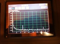
For keeping a proportion to those screens here is output noise on a Mezmerize full preamp reg with 100uF across 5 Leds Vref. It moves 10x RMS scale down from a 317 in other words, the mains hum of the pre gnd and wiring there, but look mama! No 100hz ripple. Now for using chips, opamp & discrete series like Jung's, 'super shunt' like Allen's (R.I.P.) etc. if there are subjective inclinations I can't say more than different strokes for different folks.")
For keeping a proportion to those screens here is output noise on a Mezmerize full preamp reg with 100uF across 5 Leds Vref. It moves 10x RMS scale down from a 317 in other words, the mains hum of the pre gnd and wiring there, but look mama! No 100hz ripple. Now for using chips, opamp & discrete series like Jung's, 'super shunt' like Allen's (R.I.P.) etc. if there are subjective inclinations I can't say more than different strokes for different folks.
Attachments
I simulated 26 nV TOTAL output noise from 20-20kHz (and not 26nV(SQT(Hz)!
See attachment.
/IR
Too good to be true on a real build, but a good trend non the less. Thanks for the simulations.
Hi,
No LED or Reference is anywhere near as quiet.
So it must be RC filtered to get the noise sufficiently low. So now we have the Passive components already to lower the noise, including all the attendant problems of the passives.
Or more clearly, we now have the "reference filter capacitor" actually form the primary feedback element in the two transistor feedback amp (which we call shunt regulator), so any imperfections in that capacitor are put out amplified by the active circuit.
Low noise, yes. But do we get a better result than to simply using passive circuits without amplification?
That is the question here and it is an interesting one. My gut feeling is that we have same situation here as with servo's. If one must one can make them work, to me normally they sound worse than a good coupling cap, but are conceivably cheaper (as we again in essence are dealing with an amplified capacitor, so values can be relatively small).
Ciao T
I simulated 26 nV TOTAL output noise from 20-20kHz (and not 26nV(SQT(Hz)!
No LED or Reference is anywhere near as quiet.
So it must be RC filtered to get the noise sufficiently low. So now we have the Passive components already to lower the noise, including all the attendant problems of the passives.
Or more clearly, we now have the "reference filter capacitor" actually form the primary feedback element in the two transistor feedback amp (which we call shunt regulator), so any imperfections in that capacitor are put out amplified by the active circuit.
Low noise, yes. But do we get a better result than to simply using passive circuits without amplification?
That is the question here and it is an interesting one. My gut feeling is that we have same situation here as with servo's. If one must one can make them work, to me normally they sound worse than a good coupling cap, but are conceivably cheaper (as we again in essence are dealing with an amplified capacitor, so values can be relatively small).
Ciao T
Dreamers, just wait till you try to build something for real! '-)
Its built a bit by now...like in the FFT screen post #609. Has no external loop feedback or opamp. The reference is not RC filtered, only shunt C 100uf for that FFT.
Yes, it is of course filtered. Like in the attachment.
Hi,
No LED or Reference is anywhere near as quiet.
So it must be RC filtered to get the noise sufficiently low. So now we have the Passive components already to lower the noise, including all the attendant problems of the passives.
Or more clearly, we now have the "reference filter capacitor" actually form the primary feedback element in the two transistor feedback amp (which we call shunt regulator), so any imperfections in that capacitor are put out amplified by the active circuit.
Low noise, yes. But do we get a better result than to simply using passive circuits without amplification?
That is the question here and it is an interesting one. My gut feeling is that we have same situation here as with servo's. If one must one can make them work, to me normally they sound worse than a good coupling cap, but are conceivably cheaper (as we again in essence are dealing with an amplified capacitor, so values can be relatively small).
Ciao T
Attachments
Low noise, yes. But do we get a better result than to simply using passive circuits without amplification?
Ciao T
Yep, massively better Zo characteristics. As for the ref cap, yes its audible that is why we bypass it with PP//Teflon in the more expensive builds.
Hi,
Good grief, I am bad today. I slipped a decimalpoint...
I could claim it was to see if anyone pays attention.
The 3,300uF Cap of course has 2.4 Ohm Z at 20Hz and 0.18nV|/Hz equivalent noise at 20Hz, in the midband and up a Silmic II is a few 10's mOhm...
And of course the LF rise does not exist...
Ciao T
A 3,300uF Cap is 24 Ohm at 20Hz, so in terms of noise from resistors not shunted it should give around 0.6nV|/Hz at 20Hz and less as the frequency rises.
Good grief, I am bad today. I slipped a decimalpoint...
I could claim it was to see if anyone pays attention.
The 3,300uF Cap of course has 2.4 Ohm Z at 20Hz and 0.18nV|/Hz equivalent noise at 20Hz, in the midband and up a Silmic II is a few 10's mOhm...
And of course the LF rise does not exist...
Ciao T
Hi,
Real green LED's are around 0.5uV noise at 1mA, a little less at more current, more at lower current.
You have 8pcs strung in series for around 16V reference voltage and 8uV noise.
This is around 6db better than the rather noisy LM329.
I'm not sure of the slope impedance for the LEDS, but it is usually a few ohm to 10's of Ohm. Let's take 20 Ohm, so 160 Ohm total. You add another 275R for a total of around 450 Ohm.
With a 220uF cap we have 36 Ohm at 20Hz and so 0.7nV|/Hz...
The 3dB noise corner on that assembly is 1.6Hz.
I think it would be highly desirable to feed this whole reference circuit into a CCS to minimise any AC current through the string, probably also using a J-Fet as error-amp to avoid drawing AC current through the reference chain would be good.
And it still is not really any better (except LF impedance) that a single 3,300uF Cap at the end of an RC filter chain where it matters.
It may be oldfashioned, this RC filter chain thing, but the engineers from Neumann, Technischer Aparatebau, Pulse Technology and co. knew what they where doing, in part at least evidenced by the high regard these old units are being held among the cognescenti in recording for outstanding sound quality.
Well anyway, I know what my first choice would be... ;-)
Ciao T
Yes, it is of course filtered. Like in the attachment.
Real green LED's are around 0.5uV noise at 1mA, a little less at more current, more at lower current.
You have 8pcs strung in series for around 16V reference voltage and 8uV noise.
This is around 6db better than the rather noisy LM329.
I'm not sure of the slope impedance for the LEDS, but it is usually a few ohm to 10's of Ohm. Let's take 20 Ohm, so 160 Ohm total. You add another 275R for a total of around 450 Ohm.
With a 220uF cap we have 36 Ohm at 20Hz and so 0.7nV|/Hz...
The 3dB noise corner on that assembly is 1.6Hz.
I think it would be highly desirable to feed this whole reference circuit into a CCS to minimise any AC current through the string, probably also using a J-Fet as error-amp to avoid drawing AC current through the reference chain would be good.
And it still is not really any better (except LF impedance) that a single 3,300uF Cap at the end of an RC filter chain where it matters.
It may be oldfashioned, this RC filter chain thing, but the engineers from Neumann, Technischer Aparatebau, Pulse Technology and co. knew what they where doing, in part at least evidenced by the high regard these old units are being held among the cognescenti in recording for outstanding sound quality.
Well anyway, I know what my first choice would be... ;-)
Ciao T
Hi,
Real green LED's are around 0.5uV noise at 1mA, a little less at more current, more at lower current.
You have 8pcs strung in series for around 16V reference voltage and 8uV noise.
Ciao T
Noise voltages do not add arithmetically. But you probably already knew that. It would equal the square root of the sum of the individual values squared, if totally not related. Which is almost the example here, although some coupling could occur due to poor construction techniques.
So the noise for the string of 8 would approach 1.414 uV
- Status
- This old topic is closed. If you want to reopen this topic, contact a moderator using the "Report Post" button.
- Home
- Source & Line
- Analogue Source
- Parasound JC3 Phono