I would look into the source of the 1K IMD more closely, an anti-imaging filter would not remove it so I would presume it is plain old analog IMD somewhere.
Yes, that is my understanding. The 1kHz IMD is generated by the analog section following the DAC. Since the Muse Audio has no anti-aliasing filter, there are strong image tones at 24.5/25.5kHz, 62.5/63.5kHz, 68.5/69.5kHz, 106.5/107.5khz, 112.5/113.5Khz….etc. The HF distortion response of the analog section to these “out of band” signals is what is causing the rather large magnitude 1kHz tone along with a wide spread of higher order IMD products.
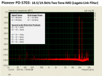
Looking at the Pioneer player, you can see that the Legato Link filter has poor rejection of the first of these image tones (24.5/25.5kHz). Compared to a brickwall filter, this results in measureable in-band 2nd order products at 5khz, 6khz, & 7kHz as well as 1kHz(although not nearly the magnitude as those seen from the Muse audio which has to deal with an array of higher frequency image tones).
If the Post-DAC filter is doing something to the signal other than a minor rolling off of the HF response, it would likely show up in a two tone test like this. My initial thought was that the capacitor is compromising the linearity of the DAC by loading down its output. This is a change that could not be “un-done” by corrective EQ of the frequency response.
I am definitely interested in seeing results of testing by SY.…On the listening tests by SY, maybe we can work through that and I am for that, make no mistake...
I will donate $20 to help with shipping cost if the testing goes forward.
In the meantime, I will contact you off list concerning ARTA testing methods.
Attachments
Yes, that is my understanding. The 1kHz IMD is generated by the analog section following the DAC. Since the Muse Audio has no anti-aliasing filter, there are strong image tones at 24.5/25.5kHz, 62.5/63.5kHz, 68.5/69.5kHz, 106.5/107.5khz, 112.5/113.5Khz….etc. The HF distortion response of the analog section to these “out of band” signals is what is causing the rather large magnitude 1kHz tone along with a wide spread of higher order IMD products.
Interesting since anti-imaging filters were made 30yr. ago with 5534's even that did not show this. One thing to look at though is for clipping at an internal filter stage, it might be useful to slowly lower the amplitude and see if it suddenly goes away. I have a media box (IIRC Amber from China or Taiwan) that cannot play a 0dB 16bit file off of a CD without hard clipping.
Last edited:
The two tone signals were -6dB below Full Scale. I also tried it at -12dB with similar results.One thing to look at though is for clipping at an internal filter stage, it might be useful to slowly lower the amplitude and see if it suddenly goes away. I have a media box (IIRC Amber from China or Taiwan) that cannot play a 0dB 16bit file off of a CD without hard clipping.
I guess it is possible that the analog stage was clipping...but would that produce the distortion products seen? I no longer have the unit, so can't investigate further with it. However one could certainly run an opamp into clipping in a measurement loop to see what distortion products get generated from the two tones. You may have peaked my curiosity just enough to give it a try
")
I'm ignorant of the Pioneer- why are the image tones still in the output? Is the "Legato Link" some sort of "we don't believe in accurate reconstruction" filter?.
Exactly. A rather soft knee filter shown on slide 3 of the measurements back in post#304.
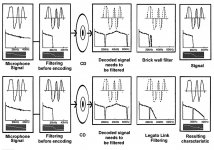
According to Pioneer literature “back in the day”…it was an attempt to restore the high frequencies present in the original recording that were removed during 16/44 encoding. See attached graphical explanation of the magical operation of Legato Link Filter.
At least with the Elite version of the Pioneer players they included a switch to turn off Legato Link.
See measurements of the PD-65 with/without in Figure 3A/3B in the attached review.
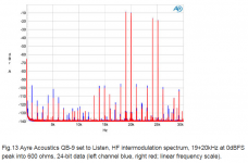
Similar approach is taken by Ayre with many of their DACs, although I think they usually use minimum phase filter rather than linear phase.
Ayre Acoustics QB-9 USB DAC Measurements | Stereophile.com
Attachments
"we don't believe in accurate reconstruction" filter? That doesn't look like poor rejection, it looks like no rejection.
Yes ala Wadia and the guys that call it apodization to appear cool.
EDIT - I see you took the words right out of my mouth.
Apodization? In the worlds I travel in, that means windowing.
As I said it sounds cooler than windowing which everyone has at least heard of.
I'd offer myself as Joe's listener and pick up all the expenses involved but I don't think he would agree. The offer is there.
Last edited:
It was my understanding that the term apodizing filter was borrowed from optical filtering technique to remove halos or airy-disks around bright objects. In audio terms it reduces pre and post ringing on impulses. The attached Ayre white paper gives some background and mention of an AES paper on the subject.
AES E-Library Antialias Filters and System Transient Response at High Sample Rates
FWIW, the Legato Link filter did have a noticeable "effect", especially on sparse percussive piano notes. Did you happen to see the measured distortion performance in the PD-65 review?(rising to 1% at 20kHz) and discussion in the text as to why that is a good thing?
Like I said before, I don't know what loading the DAC output with a capacitor may do. But if it imprints a particular HF distortion signature it could be audible even with negligible change to the frequency response.
Attachments
I'd offer myself as Joe's listener and pick up all the expenses involved but I don't think he would agree. The offer is there.
I would like to see if we can capture some 'event' first. If so, then we will have positive motivation that doesn't bias controlled listening tests even before they start. You know, make a prophecy and you likely end up with a self-fulfilling prophecy, and as we all know, bias is a very insidious problem because the person who has it hardly recognises it. So the conditions leading up to those tests are important in my view. We want a positive outcome to have a chance.
So...
I also propose that if those listening test goes ahead under the auspices of SY, then there should be another parallel one (not necessarily in time) that I propose, one I believe has less traps, or at the very least different traps. And perhaps nothing should be made public until they have both been conducted?
Controls so that the tests are valid are not negotiable. No peeking, ears only. You pick the listener...
Stuart, that is not what I meant by negotiable. Hope you can see that. I propose two different tests.
Cheers, Joe
-
Wow. Just... wow. Thanks, I really had no idea such things existed.
Now you know that I have been for some time hoping that Steve would come into the conversation. Especially with the pressure you have aimed at my way. I did admit I needed help, did I not? But no probs, I don't keep grudges, it is the outcomes that matter.
Let's see if we can turn around this thread. My attitude is simple, whatever comes out of it, let's find the truth and nothing more, right?
-
Last edited:
Good morning folks
All right..
Been reading the thread a couple of times now and I would like to try this phenomenon that you all are for or against.
So here it is:
A friend of mine have heavily modified a pcb with a CS4398 dac chip with much better capacitors, resistors and psu. I have done the same thing.
Each phase of dac output goes straight through a 2.2uF copper foil coupling cap and into the grid of a low gain tube stage (6.7dB gain)!
Grid resistor is 100K!
Everything sounds great on the test wooden plate, but I willing to try this "effect":
So my setup looks pretty much like this:
But again - My chip is CS4398!!
Can I please ask for some help to implement this? I mean, the datasheet for CS4398 say minimum load on dac output are 1K!!
This shows 300R! and the 12nF, what should be the value of this one?
I already have purchased these 0.33F caps on ebay, but the 3.3v and 5v supply on my dac board is done by some small LM1117 regulators with 15uF Sanyo oscon on the output. Are these small regulators able to handle these huge 0.33F caps??
I look forward for some nice and interesting answers
Best from
Vingborg
All right..
Been reading the thread a couple of times now and I would like to try this phenomenon that you all are for or against.
So here it is:
A friend of mine have heavily modified a pcb with a CS4398 dac chip with much better capacitors, resistors and psu. I have done the same thing.
Each phase of dac output goes straight through a 2.2uF copper foil coupling cap and into the grid of a low gain tube stage (6.7dB gain)!
Grid resistor is 100K!
Everything sounds great on the test wooden plate, but I willing to try this "effect":
So my setup looks pretty much like this:
Scenario Six:

But again - My chip is CS4398!!
Can I please ask for some help to implement this? I mean, the datasheet for CS4398 say minimum load on dac output are 1K!!
This shows 300R! and the 12nF, what should be the value of this one?
I already have purchased these 0.33F caps on ebay, but the 3.3v and 5v supply on my dac board is done by some small LM1117 regulators with 15uF Sanyo oscon on the output. Are these small regulators able to handle these huge 0.33F caps??
I look forward for some nice and interesting answers
Best from
Vingborg
I already have purchased these 0.33F caps on ebay, but the 3.3v and 5v supply on my dac board is done by some small LM1117 regulators with 15uF Sanyo oscon on the output. Are these small regulators able to handle these huge 0.33F caps??
Yes, they should be fine, the ESR of the 0.33F is fairly high and peak current to a depleted cap (worst case scenario) is likely to be well under 100mA.
But again - My chip is CS4398!!
Can I please ask for some help to implement this?
Yes, get some Vigortronics 1:1 transformers and use this scenario:
An externally hosted image should be here but it was not working when we last tested it.
Where it says AK4382 it could just as likely says CS4398.
The transformer is shown on this page, the number to look for is VTX-101-007.
They can be bought from Element14 and others and are very reasonably priced. Don't underestimate how good they sound when used this way.
Here in Australia: VTX-101-007 - VIGORTRONIX - Audio Transformer, 600 ohm, 600 ohm, Through Hole | element14 Australia
The tricky bit is the over-cooked Zobel network, but we can work through it, the values shown are only starting values, 15nF and 1K5. These will need to be tweaked, you will need an oscilloscope and some test files that you can put on a CD or play as files.
Trust me, I have done this and the results are beyond expectations, at least they were beyond mine.
Cheers, Joe
Hi Joe, could you please give references (eg Farnell part numbers) of the actual parts you are using, including the 1uF DAC +/- output pins shunt cap.Yes, they should be fine, the ESR of the 0.33F is fairly high and peak current to a depleted cap (worst case scenario) is likely to be well under 100mA.
Cheers, Joe
Dan.
My attitude is simple, whatever comes out of it, let's find the truth and nothing more, right?
-
Great. Ready to go? You already have 2/3 of your shipping costs paid for by Steve and me. Should I email you shipping addresses? Let me know who you decide to have do the listening portion, and what specific mods you want done on one of the DACs once the baselines are measured and established- I will follow your schematic exactly.
How about a Lundahl 1684 Amorph 1:1 - I have borrowed two pcs. from a friend before, maybe I can do that again!
it is in any way possible to avoid transformers in this CS4398 application?
(Because I already have been testing sound quality with several tranny's and ES9018 and I can't make them better than my high quality Sony cd-player!)
This modified CS4398 pcb I've got is actully better with my low gain tube stage than my Sony player!
An oscilloscope is possible at my brother's place
I can't hear the grass is growing, but I'm interested in this experiment - Still I'm sceptical for those audio transformers..
Best from Vingborg
Yes, they should be fine, the ESR of the 0.33F is fairly high and peak current to a depleted cap (worst case scenario) is likely to be well under 100mA.
Yes, get some Vigortronics 1:1 transformers and use this scenario:

Where it says AK4382 it could just as likely says CS4398.
The transformer is shown on this page, the number to look for is VTX-101-007.
They can be bought from Element14 and others and are very reasonably priced. Don't underestimate how good they sound when used this way.
Here in Australia: VTX-101-007 - VIGORTRONIX - Audio Transformer, 600 ohm, 600 ohm, Through Hole | element14 Australia
The tricky bit is the over-cooked Zobel network, but we can work through it, the values shown are only starting values, 15nF and 1K5. These will need to be tweaked, you will need an oscilloscope and some test files that you can put on a CD or play as files.
Trust me, I have done this and the results are beyond expectations, at least they were beyond mine.
Cheers, Joe
- Status
- Not open for further replies.
- Home
- Source & Line
- Digital Source
- Practical Implementations of Alternative Post-DAC Filtering