Thanks.The 1uF I have used 189-0147 or 100-6040 (physically smaller).
The 0.33F is 130-5058. But these can also be bought of eBay although ESR isn't specified.
You don't want ESR too low, 40-100R is usual and 130-5058 is 75R.
eBay: 5 5V 0 33F 30% V Terminal Type Super Farad Capacitors 10 PCS WS | eBay
Cheers, Joe
For forum information -
WIMA MKS2D041001K00KSSD Film Capacitor, MKS2 Series, 1 µF, ± 10%, PET (Polyester), 100 V
WIMA MKS2C041001F00KSS Film Capacitor, MKS2 Series, 1 µF, ± 10%, PET (Polyester), 63 V
PANASONIC ELECTRONIC COMPONENTS EECS0HD334V CAP, DOUBLE, 0.33F, 5.5V
In the 1uF position, have you tried other capacitor dielectric types and other form factor (smd/axial etc) ?.
So the ESR of the 0.33F supercap is somewhat important it seems.
What are the effects of lesser or greater ESR value, and have you tried other values of supercap ?.
Dan.
Last edited:
Capacitors you are talking was never soldered in circuit so it happens to be on the right track.
How do i know that i found the right point for grounding? I should target zero DC on output of I/V opamps ?
Thanks once again!
You should do so to have 0,000v offset on output (unbalanced), or very near to this value.
This is my definite favourite : 4 DAC(Iout=16mA p-p) PCM1796 @ R=10 Om + ina103kp:Круто:
View attachment 506098
nice surprise: ура:
Thank you Vovi. What is your test setup / ADC / soundcard etc?
Have you compared traditional virtual ground I-V to this both subjectively
and measurement wise. INA103 is somewhat unknown in these circles but
very highly regarded in pro audio field.
Joe - is there any reason you can't provide us with similar measurements?
It really would be appropriate at this stage from a credibility perspective.
These are pretty much what people are looking for to accompany the
subjective claims and not too hard to do these days.
PS - Joe apologies if I have missed them, don't have much time to deeply
follow this thread.
cheers
Terry
Referring to zenelectro post.
Well, I`m either one or another you address your above post to, but I would like to come with my observations to the subjects you touch.
vovi have measured a sound card (Asus Xonar D2), as seen in the Right Mark Audio Analyser. This sound card it have (as stated by manufacturer) a internal connection on board which it supposedly connect/loopback (activated through the driver software - ALT) the analogue output of the DACs to the on board ADC input. There is not known yet how in fact this connection is made, or where the loopback is placed on the card`s PCB. This so called ALT loopback it cause extremely good measurements results, one even can not reach for very high end devices. And just think, a computer environment is very different than any high end device out there... The measurements presented by vovi do not shows whatsoever influence of huge amount of EMI noises one have inside and in the power system of an computer...
I personally do not trust very much this Assus trick to shows how good their products are.
When one think at the very recent Volkswagen scandal, one can also understand better this Asus measurements approach...
Much more realistic measurements should be done in this case through a physical wired (cable) loopback between the card outputs and the ADC on board (record) inputs. For sure the results will not be the same...
Why Joe can not do such? Well, he can answer by himself, but in my opinion, if he/one should chose to do so, he/one should tie an external DAC`s I2S lines to the processor into the sound card ones, making a loopback with the on board ADC. Or modify accordingly the DACs on a sound card, to implement this filter into it. Do you think this is a simple to be done approach?
The "issue" in measuring (loopbacking) a DAC device with/without this filtering on it, is the loopback itself, the needed high end ADC, and a computer in between which may run RMAA to get similar measurements, or advanced measurement devices to connect to that loopbacked system. Who may have all these things together in his place?
I will use the opportunity here to suggest to those who intend (or insist it) to measure something on this cap approach, to work first to establish a test/measurement procedure on paper, and making it known so to be discussed first here. After a general agreement is in place regarding the measurement approach, then an in fact measurement can occur, following strictly that agreed procedure.
Having a (public) measurement approach, with clear how to do it lines, then few/many can maybe do it by themselves. The many measurements results can then be compared and analysed (here too) and a final conclusion it can be shaped so.
BTW, can we ask to vovi to do for us the same measurements on one virgin sound card and one or the same sound card modified to have this cap in place? It will such measurements be eloquent for the discussion here?
Last edited:
I use a ESS9018 K2M dac with tipical datasheet output. What components and values i should use in order to gain this effect discussed here ?
My DAC has more sources than PCM179x described in the first page (2xdigital and 3xanalog), should install supercapacitors to all of them ? Now are decoupled with 1uf||0,1uf ceramic caps.
Thanks!
An externally hosted image should be here but it was not working when we last tested it.
Yes, I have actually done this on ES9018 and it is similar to this:

Here are the changes required and they are quite simple:
Yes, you will need to cut tracks to add 3R3 and it is important the 1uF is on the DAC side as shown. Whether you add the EQ correction caps (red eclipses) is up to you, but generally we leave them out. If you decide to use them, you will need equipment to tweak FR flat.
BUT...
If memory serves me right, the ES9018 has seventeen power supply pins, some 3.3V and other 1.2V (core). How many separate regulators does it use, can you show a schematic of how this ES9018 is powered. I would indeed put one 0.33F on each one. It will be a minimum of two, but up to 4 or 5 regulators, so one per regulator. Also get a decent value 22uF/SMD in parallel with same 0.33F.
You will need some of these to finish the job:
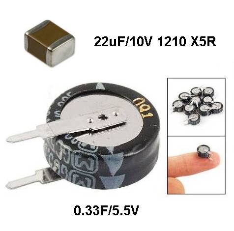
As you have probably noted, these are 0.33Farad, not uF.
Use Element14/Farnell or even eBay to them.
Cheers, Joe
Last edited:
Hi Dan
You could use more exotic that PET, but they are not that easy to get as they tend to be rated at high voltage. Maybe look for 1uF Polyprop type used for speakers - but they are typically 250V.
Farnell have these, 1uF 100V 1368024
It's just a matter of safety, no more. Imagine a 330.000uF capacitor with ESR 0.1R and calculate the peak current into that cap (33 Amp?) in a depleted state. Either you blow up the power supply or the regulator is hopefully self-protected. Generally you don't want more than around 100mA peak IMO. The question about snubber effect? That's another matter.
Cheers, Joe
In the 1uF position, have you tried other capacitor dielectric types and other form factor (smd/axial etc) ?.
You could use more exotic that PET, but they are not that easy to get as they tend to be rated at high voltage. Maybe look for 1uF Polyprop type used for speakers - but they are typically 250V.
Farnell have these, 1uF 100V 1368024
An externally hosted image should be here but it was not working when we last tested it.
So the ESR of the 0.33F supercap is somewhat important it seems.
What are the effects of lesser or greater ESR value, and have you tried other values of supercap ?.
It's just a matter of safety, no more. Imagine a 330.000uF capacitor with ESR 0.1R and calculate the peak current into that cap (33 Amp?) in a depleted state. Either you blow up the power supply or the regulator is hopefully self-protected. Generally you don't want more than around 100mA peak IMO. The question about snubber effect? That's another matter.
Cheers, Joe
Hey Joe, are you sending some DACs to SY? I'm really interested to see what he finds, and interested in the results of blind testing.
SY, what do you have for testing above the audio band? I'm interested to see what might be up there as noise.
Sending DACs to SY?
I don't actually having any of them lying around here? Nice suggestion on paper...? I am not a shop though. A USB DAC? A player? SPDIF input? What DAC chip? My preference would be a "current" DAC from B-B 179x range, followed by opamp I/V using something like LM4562 - I have also tried this type of combo on ES9018 and Ken Newton on B-B DACs.
Right now I would prefer to seek a measurement - and if we find a measurement that correlates with what we are doing (I will be seeking to find a particular behaviour) and if we find what we hope for, then any listening test wouldn't be about whether something sounds different, but more specifically if what is measured is audible. This would change the attitude from merely disproving (a negative) into some confirmation of something measurable (now positive). I do believe that the framework and indeed the motive for setting up the kind of test SY has in mind, is less likely to be biased. Yes, predisposition can affect the outcome.
What we hear (and what we want to prove) has something interesting, about the point of onset of the filter - if we not only measure an anomaly, but that the anomaly occurs at a specific point or onset in a sudden rather than gradual and at around 1-dB, then we know not only that we are hearing something, but it will be a genuine confirmation that is the cause. Whether we are able to do that, only time will tell. But if we do, how it was done will be fully disclosed here. Then we will arrange listening tests that seeks a positive outcome.
Indeed, at that point, everything will be on the table and anybody can do what they like.

Cheers, Joe
-
Last edited:
Joe - is there any reason you can't provide us with similar measurements?
It really would be appropriate at this stage from a credibility perspective.
These are pretty much what people are looking for to accompany the
subjective claims and not too hard to do these days.
PS - Joe apologies if I have missed them, don't have much time to deeply
follow this thread.
Hi Terry
Yep, as you have gathered, that is what we are aiming for and you are right, the measurement is also what I want.
I want you in the loop, also getting some help from Steve via regular email and setting up ARTA / Soundcard (compatible) setup within a short time. Might give you a call sooninsh and let you know what I am doing and any pointers/suggestions from you are welcome.
Re credibility, one way or another, whatever it is, I think it has to be something obvious and measurable, I mean, like Ken says, it is not that subtle when you hear it, like 10% distortion is not audible, it's in that kind of ballpark - so gotta be measurable, only how is the question. But I am genuinely positive it can - and with a little help from my friends?
Cheers, Joe
-
Joe what will the mod for TP Legato
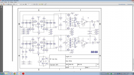
Bit hard to tell, the resolution is poor, but I assume that the two pairs of inputs are approximating a virtual ground? If so, cut the track from the DAC and insert 3R3 on both phases, then on the DAC side of 2 x 3R3, wire a 1uF film cap across that, on the DAC I repeat. If it is not virtual ground, then need to know what it is - but again I think it looks like virtual ground?
Does anybody have a clearer version of this Legato 3.1 diagram by Russ White (Buffalo)?
Cheers, Joe
Sending DACs to SY?
I don't actually having any of them lying around here? Nice suggestion on paper...? I am not a shop though ...
Indeed, at that point, everything will be on the table and anybody can do what they like.
Cheers, Joe
-
Jeez, did you miss all of the posts about this over the course of the last week or so?
It looks like everything except, I guess, testing by you and publishing results or providing your work to others to test is what's on the table.
zenelectro, Coris
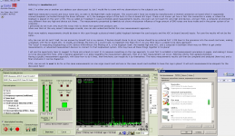
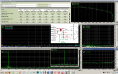
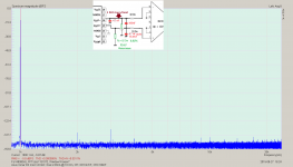
YES! I have measured a sound card Asus Xonar D2 mod 4 DAC=Iout ±16mA @ 10 Om, new Cf1=Cf2=47nF, Cf3=100nF.
External loopback (line-out - line-in): ура:
YES! I have measured a sound card Asus Xonar D2 mod 4 DAC=Iout ±16mA @ 10 Om, new Cf1=Cf2=47nF, Cf3=100nF.
External loopback (line-out - line-in): ура:
Attachments
Well, originally, the problem was lack of measurement capability and inability to do an ears only test. So I offered to do the heavy lifting. Then the issue was logistics. So several of us (including you) stepped up to cover that. Now the issue is not having DACs, though Joe sells modded DACs and can resell anything he sends me.
Could it possibly be that there really is nothing here?
Could it possibly be that there really is nothing here?
Bit hard to tell, the resolution is poor, but I assume that the two pairs of inputs are approximating a virtual ground? If so, cut the track from the DAC and insert 3R3 on both phases, then on the DAC side of 2 x 3R3, wire a 1uF film cap across that, on the DAC I repeat. If it is not virtual ground, then need to know what it is - but again I think it looks like virtual ground?
Does anybody have a clearer version of this Legato 3.1 diagram by Russ White (Buffalo)?
Cheers, Joe
Attached PDF
Greetings
Felipe
Attachments
...Could it possibly be that there really is nothing here?
Yep, unbiased scientific test awaits.
- Status
- Not open for further replies.
- Home
- Source & Line
- Digital Source
- Practical Implementations of Alternative Post-DAC Filtering