Member
Joined 2021
Hello,
I have published my 12th variant of the Q17 - a modified version of Tibi's original - on my website for the DIY hobbyists. There are PCBs (with Gerber files for download) as well as a parts list published there. For those who live in the EU I have listed the part numbers from Reichelt.de. There you can get the parts cheap.
Regards Tim
http://lautsprecher.tuschell.de/DIY/Q17.html
Hello Tibi,
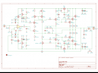
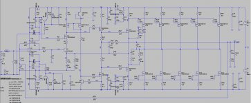
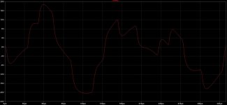
atiq19 has reappeared and wants to build on the concept with double output stage - I don't know what it is called exactly. So I simulated some hours to minimize the oscillation probability of the circuit for the different load cases. Another aspect is the frequency response, which in this circuit has very high levels in the MHz range, so I changed all the filters in the circuit.
Maybe this is an approach for you to pursue the circuit with the many parallel end transistors.
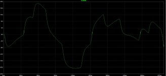
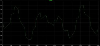
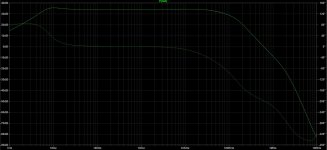
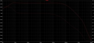
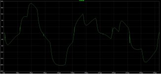
Attached is the circuit, the transient simulation results for a complex high frequency signal at the red point and for the output also the frequency response.
Regards Tim
atiq19 has reappeared and wants to build on the concept with double output stage - I don't know what it is called exactly. So I simulated some hours to minimize the oscillation probability of the circuit for the different load cases. Another aspect is the frequency response, which in this circuit has very high levels in the MHz range, so I changed all the filters in the circuit.
Maybe this is an approach for you to pursue the circuit with the many parallel end transistors.
Attached is the circuit, the transient simulation results for a complex high frequency signal at the red point and for the output also the frequency response.
Regards Tim
Attachments
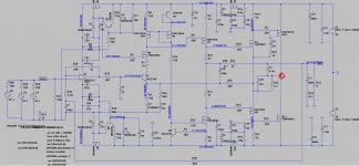
Now an idea, for a circuit with 5 pairs of power transistors. During the simulation the experiences with the triple parallel end transistors and their tendency to oscillate become visible. I have therefore added a lot of components to counteract this effect.
Another point is the voltage from the driver stage, here I reduced the very sensitive resistor R6 to 8.2 ohms. This works with this circuit, because the offset in the current damping bridge is still high enough - much higher than with the Q17.
At first sight the simulation seems as if this construct could have a playing performance. However, for me it is a virtual experiment for now.
In any case, the simplicity of the Q17 has advantages over such a construction. By this I mean that the Q17 is an ingenious amplifier, since it performs outstandingly with few components. The variant presented here is rather the attempt to compensate the deficits of MosFet as an amplifier by using a lot of components and thus still be able to realize a well playing amplifier.
Attachments
Last edited:
Hi Tim,
I can not comment on your design because do not follow my schematic.
You again have included R16 + C26 and these will increase high frequency response making amplifier unstable.
On other hand you have removed some parts - like M4 and M8 source resistors - increasing instability.
I appreciate your effort in trying various topologies.
Regards,
Tibi
Hello Tibi,
both have a system:
1. source resistors: M4 + M8 for this I did experiments a long time ago and found that the correction function of the amplifier circuit is affected with these resistors. Also in the simulation these were not advantageous. The resistor R22 turns out to be more favorable. Then I opened the current damping bridge and varied the filter from R22+L3, as well as C28 + R54 for the damping of oscillations so long that the switching needle impulses from the MosFet do not resonate, but are damped immediately. (The extension of the current damping bridge is also intended to keep the needle pulses of the power mosfet away from the cascode (via R28) - at least that was my intention.)
2. R16 + C26 results in a hump in the super high frequency range and reduces the phase rotation of the amplifier in the consonant range, this is not a promotion of instability (which is due to oscillations in the MHz range - in the Q17 this is a frequency band of 6MHz and 12MHz), since this takes place in much higher frequencies. Since the tuning of this "hump" also causes the slope to fall more steeply above 100kHz.
In the present variant with 5 power amplifiers, it was possible to lower the attenuation in the MHz range below that of the Q17, I consider this very important. Here a too early lowering of the frequency response in the audio range is to be avoided of course in any case, therefore the support of the high tone by R16+C26. The high damping in the MHz range in combination with the filters from R22+L3+C28+R54+R27+(C27+C31) is my answer to the oscillation risk. Thereby the filters of the power stage must only work in the MHz range and not attenuate the audio range, that is the audiophile goal. Conversely, it is clear that C4 and C26, which are effective in the high audio frequency, should have a very high audiophile quality. In the present case, I therefore recommend for both Wima FKP1, which, according to my experiments, sounds freer in the super high frequency than the FKP2 (I attribute this to the fact that the FKP1 has a higher impulse power and therefore works more ideally at high frequencies than the FKP2 or FKP3).
I do not want to talk up the circuit, but to give food for thought for the circuit topology.
Regards Tim


Hello Tibi,
This is undoubtedly visually successful. I am also impressed by the slim layout, which is completely impossible with my components.
Now to the sound:
If you compare this amp setup with the single version and play something with a percussion sound like Pink Floyd, which of the setups draws the cleaner bass with precision, punch and control?
One more question: what value of series resistor did you choose as source resistor of the output mosfet?
Regards Tim
Hello Tibi,
a bit off topic, but still exciting for me: the influence of the capacitor parallel to the red LED in the voltage regulation for the OPA.
I used this circuit to build the power supply for the analogue side of a PCM 1794A DAC. I soldered on the additional capacitors (in my case only 4.7nF each in the quality Wima FKP2) just after testing and so I could hear the sonic differences. With the additional capacitors, the highs were airier, more finely resolved, the background noises in the recordings were more audible and subjectively the bass seemed more voluminous (however, I attribute this to the purification of the mid and high frequencies).
I find this voltage control very impressive, as it works outstandingly with really very few resources.
Regards Tim
So far I have listened these modules on Dyaudio Emit M20 and Triangle Genese Quartet. Differences are more clear on Triangle speakers.
On Dynaudio bookshelf difference is in mainly in dynamics, two pair performing better.
On large speakers like Triangle, two pair is controlling a bit better bass response and have more dynamics.
MOSFET source resistors are 0.1ohm
Power supply is with one 500W r-core transformer, Saligny Standard rectifiers and 47000uF/100V Nichicon Gold.
Regards,
Tibi
Finally a version that can be easily serviced or upgraded if needed.Somehow you made me remember a small 30 watts russian amp that used tensile springy kanthal or nikeline made emitter resistors soldered directly to power trs pins that would disengage themselves on overcurrent .Never saw a current fuse more simple and ingenious at the same time in an amplifier.Few pictures with latest Q17 pcbs with two output pairs.
Modules have been tested and are performing exceptionally well.
Regards,
Tibi
View attachment 1053071 View attachment 1053067 View attachment 1053066 View attachment 1053068 View attachment 1053069 View attachment 1053070
Hello,
an update about my first finished Q17: it died spontaneously today.
I assume that it died of oscillation, just like many other test setups. However, it has now been in use for a good ½ year without any deficits.
I will now desolder the components and rebuild on the new layout with minimised oscillation potential, which I recently did with another Q17 that was still built on the old board, as the old board did not play with a transformer with 2x 30V.
Acoustically I had compared the versions a few weeks ago, the old Q17 play such an airy super high tone - like an old good ribbon - the new version on the other hand plays a long time audible, very fine and detailed high tone.
I suspect the cause of the old Q17's demise to be heat and diaphragm resonance of the connected speakers, as both together are toxic for the amplifier.
Regards Tim
Here are some measurements for Q17 with two output pairs. Power supply with Saligny Standard synchronous rectifiers, 47000uF, output voltage +/-56V. PCB available in first post and github.
Q17 output noise is under 1mVpp - left attached picture. This is observed with DMM as well - right attached picture with Fluke289 .
You can not hear any noise even with 92dBm speakers and your ear as close as possible to tweeter.


DC output is under 500uV.

Thermal distribution indicate clearly class B operation. Output mosfets are cold, really cold - see right picture Spot 4,5,6,7. This also confirm that there is no oscillation, as any oscillation will be translated in heat dissipated by output stage.
Power is dissipated in class A stage and regulators for opamp.


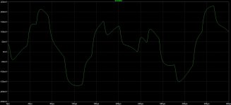
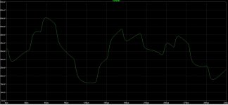
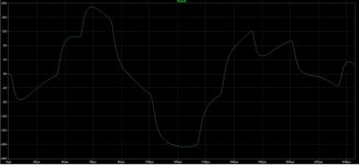
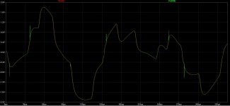
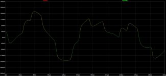
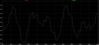
From left t right, sinus 10Hz, 100Hz, 1KHz, 10KHz, 20KHz, 30KHz, 40KHz load 8ohm/3W


Triangle 1KHz and 20KHz


Swipe from 20Hz to 20KHz in one second. Captured at 240 frames/s.
Regards,
Tibi
Q17 output noise is under 1mVpp - left attached picture. This is observed with DMM as well - right attached picture with Fluke289 .
You can not hear any noise even with 92dBm speakers and your ear as close as possible to tweeter.
DC output is under 500uV.
Thermal distribution indicate clearly class B operation. Output mosfets are cold, really cold - see right picture Spot 4,5,6,7. This also confirm that there is no oscillation, as any oscillation will be translated in heat dissipated by output stage.
Power is dissipated in class A stage and regulators for opamp.
From left t right, sinus 10Hz, 100Hz, 1KHz, 10KHz, 20KHz, 30KHz, 40KHz load 8ohm/3W
Triangle 1KHz and 20KHz
Swipe from 20Hz to 20KHz in one second. Captured at 240 frames/s.
Regards,
Tibi
Last edited by a moderator:

For the time been my 8ohm load burned while I was performing square wave test.
I'll perform nonlinear distortion measurements, Fourier and IMD as soon I get a proper load, that can sustain amplifier full power.
In the mean time, I'll enjoy musicality and resolution of this amplifier.")
Regards,
Tibi
I'll perform nonlinear distortion measurements, Fourier and IMD as soon I get a proper load, that can sustain amplifier full power.
In the mean time, I'll enjoy musicality and resolution of this amplifier.
Regards,
Tibi
👍🤗👍🤗👍🤗Buna ziua,
Am publicat cea de-a 12-a variantă a Q17 - o versiune modificată a originalului lui Tibi - pe site-ul meu pentru pasionații de bricolaj. Există PCB-uri (cu fișiere Gerber pentru descărcare), precum și o listă de piese publicate acolo. Pentru cei care locuiesc în UE, am enumerat numerele de piesă de la Reichelt.de. Acolo puteți obține piesele ieftine.
Cu respect Tim
http://lautsprecher.tuschell.de/DIY/Q17.html
View attachment 1046861
- Home
- Amplifiers
- Solid State
- Q17 - an audiophile approach to perfect sound