A quick look inside suggests the following-
1) there is space
2) The BNC's may need to be removed to access the connections.
3) A new front panel would be the clean revision. The board would mount on the panel. maybe add an extra set of minijacks to directly access the QA400. Then- mini or 1/4" jacks for the I/O? The 1/4" jacks will make for larger and more expensive cables etc. but it may be possible to use the existing holes and panel.
Respinning the board for this should be too difficult. The 1/4" stereo PC mount connectors are large footprint which may force a shift to surface mount. The BNC's would be removed and wires connected to the pads. And two wires are needed for the USB power. Fortunately it would not go past the USB2 limit. I may be able to use a charge pump and eliminate the expensive DC-DC converter.
Demian if your going to go to this extent why don't you just rip the QA400 OPA1641 right out. The only reason QuantAsylum used it is because it's rail to rail and settles fast.
The op amps are powered from a single ended 10V on-board dc-dc converter. If you can add Vcom to the THAT part your in business. This would eliminate two OPA1641 from the QA400. Shortening the signal path certainly wouldn't hurt. It would give you full control over input Z. The ADC enjoys a very low Z...low noise source. And you would be balanced all the way. None of this interface hassle.
Last edited:
Removing through hole BNC connectors is pretty easy, swapping CODECs or opamps on a board is more work and more risky. I'll leave that to Matt. I don't think the performance would be increased enough to justify the effort. And flying wires to surface mount pads can be really fragile.
The THAT parts run on a higher rail + split supply and need an output attenuator to scale for the QA400. Its possible that one of the -6 dB parts (THAT 1206) would work without the attenuator but still need to be sure it wont swing past the safe limits of thecodec or a fried codec could result.
Matt mentioned making a higher performance variation. I'll wait for that. Meanwhile I will redo the PCB.
Removing through hole BNC connectors is pretty easy, swapping CODECs or opamps on a board is more work and more risky. I'll leave that to Matt. I don't think the performance would be increased enough to justify the effort. And flying wires to surface mount pads can be really fragile.
The THAT parts run on a higher rail + split supply and need an output attenuator to scale for the QA400. Its possible that one of the -6 dB parts (THAT 1206) would work without the attenuator but still need to be sure it wont swing past the safe limits of thecodec or a fried codec could result.
Matt mentioned making a higher performance variation. I'll wait for that. Meanwhile I will redo the PCB.
A little mini PCB the size of an SOIC is all that's needed. But if you don't want to go there.
A little mini PCB the size of an SOIC is all that's needed. But if you don't want to go there.
For which function? Maybe I don't understand your suggestion?
For which function? Maybe I don't understand your suggestion?
I wasn't suggesting replace in a codec. That would have to done by Matt. By passing op amps could be done with a breakout board.
But on second thought. Any add on or mod would have to be handled by all skill levels and SMT is hard to work with.
I did a little bit of work on the QA400 with Matt during the beta testing. There is a rise in the noise floor from input loading from about 100Hz down, or was it 1K, which looks a bit like 1/f noise. We were playing around with input and Vcom components to see if there is a difference. I did at one point have the 100K Vcom resistors down to 10k as Crystal recommends in there app note. IIRC it did clean up a bit of hash. I think there is a bit of wiggle room for improvement at the input but this is all experimental.
No doubt you had some suggestions for Matt on improving the QA400 and the answer was "We cant' meet our price target doing any more than we have" or something like that. On the other hand software changes are no problem.
Guys,
My $.02... The QA400 is a well priced product with great features for the average to above average DIYer. ARTA (or similiar software) is decent with a good USB audio interface (such as the EMU 0204) is a very reasonable combo for the average or above average DIYer. The issue we all run into is high voltage measurement with either system. In order to measure a power amp, some sort of interface needs to exist to divide the voltage. There are many choices, but for me, I just want something simple and low cost. I also am not interested in modifying an existing great quality piece for super low loop back distortion baselines. 0.00015% THD is way below my expectations and anything I would be building and testing should be above this baseline.
I think a decent interface that is simple, affordable and allows the DIYer to test a power amp is all that is required. Expansion on the interface would be user preference.
Thanks for all of your input to this topic.
Dave
I don't have the circuit for the QA400 and reverse engineering it is not high on my want to do list so I don't know what's there. Removing BNC's is pretty easy for a DIY'er. Surface mount parts on a $250 box would be lots less interesting for most. I'm sure a small improvement may be possible but difficult from parts tweaking on the board.
I'm partway through the rework. Its actually a pretty simple retrofit.
A key question needs resolution- how much max out is necessary? The QA400 max output is 1.41V RMS That is not enough to drive a power amp to clipping. The traditional generators in something like an ST1700 or an HP339 are around 3V or so. if that is enough I can simplify the circuit a bunch. Next related question- max input without an external attenuator? Is 3V enough? That is more than the rated max for a standard CD player but commercial preamps are often capable of 7-10V RMS and some much more.
A key question needs resolution- how much max out is necessary? The QA400 max output is 1.41V RMS That is not enough to drive a power amp to clipping. The traditional generators in something like an ST1700 or an HP339 are around 3V or so. if that is enough I can simplify the circuit a bunch. Next related question- max input without an external attenuator? Is 3V enough? That is more than the rated max for a standard CD player but commercial preamps are often capable of 7-10V RMS and some much more.
I'm partway through the rework. Its actually a pretty simple retrofit.
A key question needs resolution- how much max out is necessary? The QA400 max output is 1.41V RMS That is not enough to drive a power amp to clipping. The traditional generators in something like an ST1700 or an HP339 are around 3V or so. if that is enough I can simplify the circuit a bunch. Next related question- max input without an external attenuator? Is 3V enough? That is more than the rated max for a standard CD player but commercial preamps are often capable of 7-10V RMS and some much more.
3V seems like plenty. IIRC the 339A is 1Vrms FS in the 0dB range.
yes-- all in one box
")
A quick look inside suggests the following-
1) there is space
Respinning the board for this should be too difficult. The 1/4" stereo PC mount connectors are large footprint which may force a shift to surface mount. The BNC's would be removed and wires connected to the pads. And two wires are needed for the USB power. Fortunately it would not go past the USB2 limit. I may be able to use a charge pump and eliminate the expensive DC-DC converter.
I checked and the HP 339A will deliver 3V into 600 Ohms. Same as the ST1700. I'll make 3.16V (+10 dBV) the target and see what I can do.
My tech is up for building boards and cables (but he has not actually done it yet and has many other distractions) so I may be able to offer assembled kits. More as soon as I know what I got myself into.
My tech is up for building boards and cables (but he has not actually done it yet and has many other distractions) so I may be able to offer assembled kits. More as soon as I know what I got myself into.
It came quickly...
I ordered one, and it arrived very quickly.
Surprised me.
Turned it on after *reading* the manual and the inserted note.
I had "issues" with the install on XP SP2.
First, my SP2 has/had "Windows Installer" 3.0 and this needs 3.1, iirc.
Royal PIA to find it, as Mucroshaft's site says it's not there, but much searching brought me to a Mucroshaft forum post that gave a direct link to the ultra secret hidden location of the no longer supported software. (Why, Mucroshaft, why??)
Installed that...why? Because to put on .Net Framework 4.0 or higher, you need 3.1 Windoze Installer... (of course you do...). DOH!
Found that software *somehow* because that too was not possible to find by a direct search on Mucroshaft's own website...
Installed that, and the program ran. Yay!
But that messed up the way regular XP folders worked, since now if you click on a file to preview it, the entire folder decides to flip the order of sorting... and *then* you can preview. Very funky. Ended up having to revert the OS back to before .Net Framework was installed, and uninstalling the QA software. Folders seem to work properly again. Yay.
Did the loopback test. Noted significant difference in harmonics between the Lch and Rch in loopback. More spurious harmonics showing up on (iirc) Rch (the red trace)! Possibly a defective unit?? Anyone else notice this? I did not save the trace, will have to redo and save.
Makes note, join the QA forum, assuming there is one.
Did not calibrate the unit. Went directly to testing with basic bench oscillator. Observed awful harmonic components, assumed unit was working.
Next threw together fail safe probe adapter, two female BNCs with a simple 50k/1k divider between, for safe testing of amps.
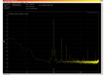
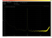
Tested bench mule, McIntosh 50-W-2 amp. Results shown. Merely jacked up variable gain on McIntosh to hit -7db on QA display and went with that...
Next tested my own Symphony No. 1 amplifer. (required marching the gear to listening room) Results shown. Not bad at all. Just a little bit of 3rd shows. Power level unclear, but certainly not at 1 watt, somewhat higher, how high, didn't bother to measure. (very scientific, eh?)
Wished that there was a way to change at least the colors of the traces and to put a title into the graph display.
Also wished for a way that is/was better than a screen grab to save the results as a graph... (not to mention recalling old tests, and overlaying them, even scaling and changing the scale, etc...).
Pretty happy so far with the results.
Important to note this box works in real time, not just snapshots, so in theory you could dork something and see the result. I like that.
I ordered one, and it arrived very quickly.
Surprised me.
Turned it on after *reading* the manual and the inserted note.
I had "issues" with the install on XP SP2.
First, my SP2 has/had "Windows Installer" 3.0 and this needs 3.1, iirc.
Royal PIA to find it, as Mucroshaft's site says it's not there, but much searching brought me to a Mucroshaft forum post that gave a direct link to the ultra secret hidden location of the no longer supported software. (Why, Mucroshaft, why??)
Installed that...why? Because to put on .Net Framework 4.0 or higher, you need 3.1 Windoze Installer... (of course you do...). DOH!
Found that software *somehow* because that too was not possible to find by a direct search on Mucroshaft's own website...
Installed that, and the program ran. Yay!
But that messed up the way regular XP folders worked, since now if you click on a file to preview it, the entire folder decides to flip the order of sorting... and *then* you can preview. Very funky. Ended up having to revert the OS back to before .Net Framework was installed, and uninstalling the QA software. Folders seem to work properly again. Yay.
Did the loopback test. Noted significant difference in harmonics between the Lch and Rch in loopback. More spurious harmonics showing up on (iirc) Rch (the red trace)! Possibly a defective unit?? Anyone else notice this? I did not save the trace, will have to redo and save.
Makes note, join the QA forum, assuming there is one.
Did not calibrate the unit. Went directly to testing with basic bench oscillator. Observed awful harmonic components, assumed unit was working.
Next threw together fail safe probe adapter, two female BNCs with a simple 50k/1k divider between, for safe testing of amps.
Tested bench mule, McIntosh 50-W-2 amp. Results shown. Merely jacked up variable gain on McIntosh to hit -7db on QA display and went with that...
Next tested my own Symphony No. 1 amplifer. (required marching the gear to listening room) Results shown. Not bad at all. Just a little bit of 3rd shows. Power level unclear, but certainly not at 1 watt, somewhat higher, how high, didn't bother to measure. (very scientific, eh?)
Wished that there was a way to change at least the colors of the traces and to put a title into the graph display.
Also wished for a way that is/was better than a screen grab to save the results as a graph... (not to mention recalling old tests, and overlaying them, even scaling and changing the scale, etc...).
Pretty happy so far with the results.
Important to note this box works in real time, not just snapshots, so in theory you could dork something and see the result. I like that.
Attachments
I ordered one, and it arrived very quickly.
Surprised me.
Turned it on after *reading* the manual and the inserted note.
I had "issues" with the install on XP SP2.
First, my SP2 has/had "Windows Installer" 3.0 and this needs 3.1, iirc.
Royal PIA to find it, as Mucroshaft's site says it's not there, but much searching brought me to a Mucroshaft forum post that gave a direct link to the ultra secret hidden location of the no longer supported software. (Why, Mucroshaft, why??)
Installed that...why? Because to put on .Net Framework 4.0 or higher, you need 3.1 Windoze Installer... (of course you do...). DOH!
Found that software *somehow* because that too was not possible to find by a direct search on Mucroshaft's own website...
Installed that, and the program ran. Yay!
But that messed up the way regular XP folders worked, since now if you click on a file to preview it, the entire folder decides to flip the order of sorting... and *then* you can preview. Very funky. Ended up having to revert the OS back to before .Net Framework was installed, and uninstalling the QA software. Folders seem to work properly again. Yay.
Did the loopback test. Noted significant difference in harmonics between the Lch and Rch in loopback. More spurious harmonics showing up on (iirc) Rch (the red trace)! Possibly a defective unit?? Anyone else notice this? I did not save the trace, will have to redo and save.
Makes note, join the QA forum, assuming there is one.
Did not calibrate the unit. Went directly to testing with basic bench oscillator. Observed awful harmonic components, assumed unit was working.
Next threw together fail safe probe adapter, two female BNCs with a simple 50k/1k divider between, for safe testing of amps.
Tested bench mule, McIntosh 50-W-2 amp. Results shown. Merely jacked up variable gain on McIntosh to hit -7db on QA display and went with that...
Next tested my own Symphony No. 1 amplifer. (required marching the gear to listening room) Results shown. Not bad at all. Just a little bit of 3rd shows. Power level unclear, but certainly not at 1 watt, somewhat higher, how high, didn't bother to measure. (very scientific, eh?)
Wished that there was a way to change at least the colors of the traces and to put a title into the graph display.
Also wished for a way that is/was better than a screen grab to save the results as a graph... (not to mention recalling old tests, and overlaying them, even scaling and changing the scale, etc...).
Pretty happy so far with the results.
Important to note this box works in real time, not just snapshots, so in theory you could dork something and see the result. I like that.
Bear all the QA400 have a difference between channels. It the Crystal codec that's at fault.
You can do an overlay. You can change the scale.
It wouldn't hurt to read the manual. Just click on help and up comes the PDF.
Also wished for a way that is/was better than a screen grab to save the results as a graph... (not to mention recalling old tests, and overlaying them, even scaling and changing the scale, etc...).
Bear, you can save traces as a data table which you can import in 3rd party graphing software. I'm using Dplot but even M$ Excell can do it.
That gives you complete freedom; I need that to get pub quality graphs.
jan
I'll look into Dplot.
There was some software that I learned of, but lost track of that would take scanned graphics or otherwise acquired graphs and turn them into publishing quality graphs. Maybe it was the Dplot?
Still, I didn't see a way to make any notes on the screen, with the plot. That would be nice, along with being able to change the trace colors...
Davada, I have read the pdf manual... no problem opening up the pop ups over buttons and knobs... thanks.
As far as the codec is concerned, is it always the Rch that is worse than the Lch? On my unit it is significantly worse. Many harmonically related spurs. It will be a week probably before I will be back and able to run the loop back test and post a graph of the two channels overlaid. Anyone able to post their loopback graphs? (scrn prnt) is what I did for the ones I posted... that and a quick trip to photoshop to convert to jpeg.
If it is the same channel that is always worse, I am wondering if perhaps two chips could be run slaved in parallel, and then only the "good" channel used?? I think the harmonics on the "bad" channel are 6-10dB higher than the good, and stand up over the grass in the noise floor. Not good.
Along those lines, if there was a way to automatically subtract these harmonics (like a 'cal file') from that channels measurements, then i suppose it wouldn't be much of a problem... otherwise how does one know if it is the DUT or the box making the harmonics??
_-_
Last edited:
I'll look into Dplot.
There was some software that I learned of, but lost track of that would take scanned graphics or otherwise acquired graphs and turn them into publishing quality graphs. Maybe it was the Dplot?
Still, I didn't see a way to make any notes on the screen, with the plot. That would be nice, along with being able to change the trace colors...
Davada, I have read the pdf manual... no problem opening up the pop ups over buttons and knobs... thanks.
As far as the codec is concerned, is it always the Rch that is worse than the Lch? On my unit it is significantly worse. Many harmonically related spurs. It will be a week probably before I will be back and able to run the loop back test and post a graph of the two channels overlaid. Anyone able to post their loopback graphs? (scrn prnt) is what I did for the ones I posted... that and a quick trip to photoshop to convert to jpeg.
If it is the same channel that is always worse, I am wondering if perhaps two chips could be run slaved in parallel, and then only the "good" channel used?? I think the harmonics on the "bad" channel are 6-10dB higher than the good, and stand up over the grass in the noise floor. Not good.
Along those lines, if there was a way to automatically subtract these harmonics (like a 'cal file') from that channels measurements, then i suppose it wouldn't be much of a problem... otherwise how does one know if it is the DUT or the box making the harmonics??
_-_
Bear do the calibration first. Then check again. 10dB is too much of a difference. I meant a little different but not hat much. You can always send the unit back but before you do email Matt at Support@QA or what ever it is. Some of the units are better than others in terms of the noise floor. But no more than 3dB. Mine is bit grassier on the right channel.
I wish I could do more with the graphics as well. Change color etc.
I have harmonically related spurs... the grass is very close.
The next thing I will try is to run the output of my partially crippled Levear/Panasonic VP7725A oscillator as the source and compare channels. That will show something since that source is known to be super low distortion, and external to the QA box, and it can measure itself at the same time...
I can do the calibration, but I was looking at "shape" not absolute levels.
I'm not sure how the internals work, but is it "legal" to swap the L/R osc outputs? I think I did that, iirc, and the spurs were still on the "red" channel.
Could be a funky box. Got to also rule out cables, just to be 100% sure.
So, to sum up no one else has seen harmonically related spurs above the grass on loopback?
Last edited:
- Home
- Design & Build
- Equipment & Tools
- QuantAsylum QA400 and QA401