I have harmonically related spurs... the grass is very close.
The next thing I will try is to run the output of my partially crippled Levear/Panasonic VP7725A oscillator as the source and compare channels. That will show something since that source is known to be super low distortion, and external to the QA box, and it can measure itself at the same time...
I can do the calibration, but I was looking at "shape" not absolute levels.
I'm not sure how the internals work, but is it "legal" to swap the L/R osc outputs? I think I did that, iirc, and the spurs were still on the "red" channel.
Could be a funky box. Got to also rule out cables, just to be 100% sure.
So, to sum up no one else has seen harmonically related spurs above the grass on loopback?
Yes it's ok to swap channels. The difference is on the capture side. I never use the pulsed sine output of the gens just an external osc.
All the capture does is measure.
I would help if you put some screen shots up.
You can tie the input channels together and use a single input source. Then you have an A-B.
Last edited:
screen shots will have to come later since I have to do two things.
First configure another laptop by installing the OS and all drivers, plus installing the QA software. The install of .Net framework seemed to have messed up my main laptop. So, I'll take a spare and use it just for measurements. I'll put up with the data transfer via thumb drive for now.
Then I have to be with the QA, I am away until the end of the week. Sorry I did not capture the problem, but it was the first time running, and I figured it was more likely user error than a problem inside the QA. So, I decided it was best to wait and see what transpired...
_-_-
After reading Bear's notes I thought I would check mine. There are a lot of possibilities to check and here are the highlights-
First loopback
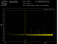
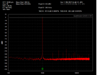
Clearly the right channel is worse than the left.
Then from an external generator (with much lower distortion than this shows)
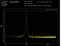
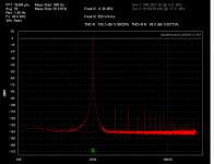
And finally through the modified QA400 interface in loopback (gain set to 6 dB on the output and approx -12 dB on the return,(need to adjust) with +/- 10 V bench supplies

I don't know why the distortion is lower with the external interface. It could be the low impedance drive and higher input impedance?
My next task is testing the charge pump supply.
First loopback


Clearly the right channel is worse than the left.
Then from an external generator (with much lower distortion than this shows)


And finally through the modified QA400 interface in loopback (gain set to 6 dB on the output and approx -12 dB on the return,(need to adjust) with +/- 10 V bench supplies


I don't know why the distortion is lower with the external interface. It could be the low impedance drive and higher input impedance?
My next task is testing the charge pump supply.
This looks like a very interesting product, been following this thread for a few months and have been considering buying an QA400 but the interface of it being limited to only 1Vrms in/out was something that made me reluctant to spend money on it.
Not that I couldnt make an external interface myself, but I prefer spending my time and money on designing and building audio devices instead.
Which is why I find 1audio's interface an interesting solution, especially if it can be bought pre built or alternatively, bare PCB's could be made available.
I don't know why the distortion is lower with the external interface. It could be the low impedance drive and higher input impedance?
Your input got lowered --- near zero in first 2.... -3.5dB on last test. Run it again with higher - zero - level and then compare.
THX-RNMarsh
I note that many of the sound cards and similar products have asymmetry in pcb layout. It often results in cross-talk digital pickup on one channel more than another. Several 'fixes' to other brands have been to reroute parts/wire routes etc. This QA400 difference appears to be the same issue.
Thx-RNMarsh
Thx-RNMarsh
Last edited:
Check out another high rez ADC system from Linear X Systems. Model LX721 analyzer. Data shows much lower distortion levels can be accurately measured compared to QA400. [32 bit vs 24 bit]
Thx-RNMarsh
Thx-RNMarsh
Last edited:
Just little off topic or maybe not so off topic, has anyone checked out the products at MiniDSP.com? A lot of very interesting stuff there at reasonable prices. All by DIYers.
Check out another high rez ADC system from Linear X Systems. Model LX721 analyzer. Data shows much lower distortion levels can be accurately measured compared to QA400. [32 bit vs 24 bit]
Thx-RNMarsh
But check out the prices. No comparison really.
Demian, et al, yes the red trace is close to what I see. But I have "fatter" and "thicker" grass and I think at a slightly higher level. However the yellow trace is entirely *free* of the harmonics on mine! However I don't think my noise floor hits as low as -140. It looks to be sitting between -130 and -125!!
I am running off a laptop, with the PS plugged in, iirc. Although I think I looked and with it unplugged it made no difference. I am wondering if the internal noise on the USB power/data lines could account for any of this. I know for certain that it does have an effect on "Pro Tools" type interface boxes (audio recording/
editing software/hardware)
So, perhaps my yellow trace side is working *better* than it ought??
A few more examples/samples from other units might give a statistically reasonable cross section regarding performance...
Regarding MiniDSP I am looking at the possibility of using an external clock for the MiniDSP USBStreamer. I think I have found a method to do so. I am close to finishing the layout of an isolated interface board. If it works as intended, I will be able to get 8 channels in and 8 channels out (10 each with an add-on board), with a clean master clock.
I have also prepared the design for the use of an externally applied master clock, so that the clock can be chosen freely (as long as they are 24.576/22.5792MHz) and placed close to the converters. The internal clocks from the USBStreamer have too much jitter in my opinion.
When this is done I plan to design an ADC/DAC board to connect to this interface board.
Hi Bear,
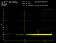
I dug out my QA400 and took some screen shots.
This is an overlay. Green is the left ch and red is the right.
192k. I'll post another at 48k
This is using the left out gen.
The 4th pic is with the gen running but not connected to either input.
You can see the crosstalk into the right channel but the left channel doesn't seem to be effected.
Attachments
Last edited:
Just little off topic or maybe not so off topic, has anyone checked out the products at MiniDSP.com? A lot of very interesting stuff there at reasonable prices. All by DIYers.
I spent some time with the Minidsp guy at AES last year. They are very together. Not DIY really but pro operation trying to eke out a living in Hong Kong. The boxes are good and they are among the best for XMOS design.
Your input got lowered --- near zero in first 2.... -3.5dB on last test. Run it again with higher - zero - level and then compare.
THX-RNMarsh
I tried that with the loopback, the distortion was still much higher. I need to rework the prototype to get unity gain through it.
davada, ur results appear to suggest that the source of the "extra" harmonics is in the generator side? Also I think I see your THD number is ~0.003%? That seems higher than spec??
I hope to be able to check a few more things over the weekend, including taking the osc from the VP-7725 and seeing how that looks, also doing the shorted input test...
Time permitting I could try running the output of the two gen channels to the VP-7725 and see how they stack up as well...
Anyone besides Demian, Davada and me actually have the box??
_-_-
I spent some time with the Minidsp guy at AES last year. They are very together. Not DIY really but pro operation trying to eke out a living in Hong Kong. The boxes are good and they are among the best for XMOS design.
I thought their product line was a bit too developed for DIY. No DIYer has that kind of time unless retired. The USB stick is just what I need to get going.
davada, ur results appear to suggest that the source of the "extra" harmonics is in the generator side? Also I think I see your THD number is ~0.003%? That seems higher than spec??
I hope to be able to check a few more things over the weekend, including taking the osc from the VP-7725 and seeing how that looks, also doing the shorted input test...
Time permitting I could try running the output of the two gen channels to the VP-7725 and see how they stack up as well...
Anyone besides Demian, Davada and me actually have the box??
_-_-
I probabaly do. Or similar-something like it.
-RM
Sorry? probably do? lost you on the curve...
----------
Fwiw, I looked again at the QA site at their own images for each channel and noticed that they too are showing similar harmonic spurs. Now with 20-20 hindsight I realize the significance of what is being shown...
----------
Fwiw, I looked again at the QA site at their own images for each channel and noticed that they too are showing similar harmonic spurs. Now with 20-20 hindsight I realize the significance of what is being shown...
Regarding MiniDSP I am looking at the possibility of using an external clock for the MiniDSP USBStreamer. I think I have found a method to do so. I am close to finishing the layout of an isolated interface board. If it works as intended, I will be able to get 8 channels in and 8 channels out (10 each with an add-on board), with a clean master clock.
I have also prepared the design for the use of an externally applied master clock, so that the clock can be chosen freely (as long as they are 24.576/22.5792MHz) and placed close to the converters. The internal clocks from the USBStreamer have too much jitter in my opinion.
When this is done I plan to design an ADC/DAC board to connect to this interface board.
Sounds very interesting. what is your current progress... what has been done to date? And, what still needs to be done..... ETA?
-RM
- Home
- Design & Build
- Equipment & Tools
- QuantAsylum QA400 and QA401


