Their own spec page says the ac input z is 10k. If its non-inverting opamp... makes no sense to me either. But if its inverting ---?
Thx-RNMarsh
The input is as I posted a few posts ago with a bit of added QA circuitry in front.
So how are we going to make the input Z higher (100K) while keeping noise and distortion low as possible?
Thx-RNMarsh
The problem is with getting the VCOM bias to the ACD inputs. If this could be done with out
loading the the source I think better result may be had. But this is a task for QA.
The OPA1632 would have been a better choice but it requires a split supply.
I try removing some of the input parts this weekend and see if it make a difference.
But I know Matt has already been through this. He did try to clean things up more just before the QA400 launch.
Well, for what its worth.... I changed the input coupling cap to a 22m/25v bipolar type and the 2H came down to about where it should be. But those higher harmonics which should not be there -- they are still there.
From looking at #524, Matt shows input configuration schematic with 10K values. There is no reason those cant be increased to much higher value.
-RNM
From looking at #524, Matt shows input configuration schematic with 10K values. There is no reason those cant be increased to much higher value.
-RNM
Last edited:
Well, for what its worth.... I changed the input coupling cap to a 22m/25v bipolar type and the 2H came down to about where it should be. But those higher harmonics which should not be there -- they are still there.
From looking at #524, Matt shows input configuration schematic with 10K values. There is no reason those cant be increased to much higher value.
-RNM
Rick those schematics are copies from the data sheets. They are for illustration.
Sorry. I know you can't get the context of the discussion. It was a long period of my involvement in the beta testing. The email chain goes on for miles. Matt sent those so he did'nt have to draw a schematic for me.
The values show are Crystal's recommendation. The actual VCOM source resistance used in the QA400 is 100K.
On my sample (preproduction) I ran into the same 10K input Z issue. It turned up when I was going through the cal process. When i measure the voltage I got one reading. When connected to the input I got another. The load Z was low enough to produce an error (.1%) that I could see.
10K for the input is not that big a deal. At the level it operates at you are connecting to mobile devices (iPhones etc.) and its at headphone levels and impedances.
I'll collect some data in the morning to share on input and output characteristics. With a buffer (the interface board) a lot of the junk goes away.
Some QA400 measurements
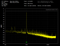
Here are some measurements of my QA400 under different conditions.
The source is my tweaked KH4400. At present when measured with the 725 at 3V out the second harmonic is at -127, the third harmonic is at -136 and the rest around -145. I have some more ideas for it but its good enough for now.
Fist the QA400 is running from my laptop. When the charger is connected its not to useable. As is obvious the noise floor jumps a lot. I tried several grounding tricks with no success.
Attachments
more measurements
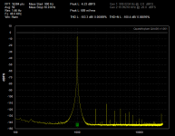
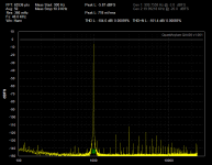
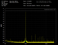
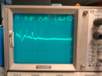
Here are three more measurements. The first a high res plot from KH4400 to QA400. The second, with a seperate ground connection from the QA400 to the chassis of the KH4400. And the third the KH4400 when connected to the QA400 measures by the 725.
1) use a separate ground connection (removes a fair portion of the junk).
2) The QA400 residuals are low but the analog limits are significantly lower.
3) not shown, the distortion increases a little (3rd increases 3 dB) when the source is 50 Ohms over 600. I don't think this is significant.
Scaling on the scope photo- top line is -100 dB. 10 dB/ vertical division, monitor out from the 725.
Next up, in a while will be inserting the interface board prototype.
Attachments
Interface board issues
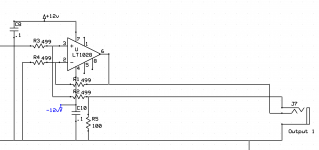
I'm testing the prototype of the interface board and a key issue jumps out- operating the output at 1.5V we run into noise issues. The 25K resistors on the input of the output driver limit the noise floor. With 10V out its at the -100 dB level, however at .7V in the SNR turns into approx 80 dB. Not enough. Back to the drawing board for this. I may need to do it discretely. The other option is to put the 20 dB of gain back in and attenuate the output to get the SNR back.
Doing it with separate parts requires 3 opamps and 10 precision (.1%) resistors. Using the integrated driver really simplifies the problem. But any level below 3V will have noise limited measurements.
The sketch below shows my proposed work around. it uses 4 precision resistors and the output gain can be adjusted through the resistor ratios. It follows the load through a form of remote sensing on the return line. This way if there are ground noise issues between the chassis it should work around them.
Attachments
Rick those schematics are copies from the data sheets. They are for illustration.
Sorry. I know you can't get the context of the discussion. It was a long period of my involvement in the beta testing. The email chain goes on for miles. Matt sent those so he did'nt have to draw a schematic for me.
The values show are Crystal's recommendation. The actual VCOM source resistance used in the QA400 is 100K.
Mine reads 10K. Are you saying it should be higher - like 100K? Do I have a non-production/early pre-production model QA400?
-RNM
Last edited:
Here are some measurements of my QA400 under different conditions.
The source is my tweaked KH4400. At present when measured with the 725 at 3V out the second harmonic is at -127, the third harmonic is at -136 and the rest around -145. I have some more ideas for it but its good enough for now.
Fist the QA400 is running from my laptop. When the charger is connected its not to useable. As is obvious the noise floor jumps a lot. I tried several grounding tricks with no success.
The QA400 does not show the low levels which you get with the ShibaSoku 725 analyzer.... same results with me.... the 2H and 3H are not accurate in level and there should be no harmonics displayed above 3H as the source doesn't have them. Your data is like mine.
Thx-RNMarsh
Source for test equip manuals-
BTW -- a good source of out-of-print test equipment manuals (such as 339A) is: www.Artekmanuals.com
Thx-RNMarsh
BTW -- a good source of out-of-print test equipment manuals (such as 339A) is: www.Artekmanuals.com
Thx-RNMarsh
Here are some measurements of my QA400 under different conditions.
The source is my tweaked KH4400. At present when measured with the 725 at 3V out the second harmonic is at -127, the third harmonic is at -136 and the rest around -145. I have some more ideas for it but its good enough for now.
Fist the QA400 is running from my laptop. When the charger is connected its not to useable. As is obvious the noise floor jumps a lot. I tried several grounding tricks with no success.
If I understand your setup correctly the two screen shots are of the QA400 (KH4400 source) with the laptop charger connected and not connected.
I do not experience any significant increase in noise if my laptop is powered by battery or charger. I wonder if some laptops behave better than others. I am using a Dell XPS M1530.
- Home
- Design & Build
- Equipment & Tools
- QuantAsylum QA400 and QA401