Idealizized means using Vituix to simulate a Dipole using the piston diameter in the diffraction tool with the Open Baffle box checked.What do you mean by "idealized"? I'm just getting more confused here.
The maximum output will always be straight in front of the driver in any configuration, a dipole will have nulls at the 90 degree points and a cardioid will have the greatest rejection at the rear, in between those two the cancellation moves around. Unticking Open baffle will just simulate an ordinary box speaker baffle diffraction.If you use the diffraction tool and untick "open baffle", there's an increase in the bass response straight ahead. How is there then no loss in the OB straight ahead?
Yes, but the dipole will have less low frequency output straight ahead than an ordinary box. An active cardioid is an ordinary box except for the rear radiation, so the output straight ahead is not affected (assuming no reinforcement from reflections), right?The maximum output will always be straight in front of the driver in any configuration, a dipole will have nulls at the 90 degree points and a cardioid will have the greatest rejection at the rear, in between those two the cancellation moves around. Unticking Open baffle will just simulate an ordinary box speaker baffle diffraction.
Straight ahead is the part that makes no sense. An equalized dipole that does not use a huge baffle will have less output all over at low frequencies than a box speaker using the same driver. But whatever output there is will always be concentrated in the forward and rearward directions. The polar plot shown before of the dipole shows that.Yes, but the dipole will have less low frequency output straight ahead than an ordinary box. An active cardioid is an ordinary box except for the rear radiation, so the output straight ahead is not affected (assuming no reinforcement from reflections), right?
So, why would an active cardioid (box speaker without rear radiation) not allow more LF output than a passive cardioid (open baffle in LF magnitude)?Straight ahead is the part that makes no sense. An equalized dipole that does not use a huge baffle will have less output all over at low frequencies than a box speaker using the same driver. But whatever output there is will always be concentrated in the forward and rearward directions. The polar plot shown before of the dipole shows that.
Hi,
both dipole and cardioid are first order gradient systems, can be made from two monopoles. This is nice and quick experiment to do in VituixCAD since it has ideal monopoles available (driver with no data loaded to it).
One of the monopoles is inverted and some distance (d) between them and dipole pattern emerges, nulls to 90 degree off-axis below "dipole null" which happens when wavelength is d. Here d is 0.1m so null happens at 3430Hz.
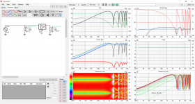
If the other monopole is delayed the nulls start to turn to bigger angle than the 90 degrees and when delay equals d you have cardioid.
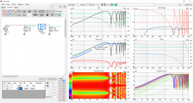
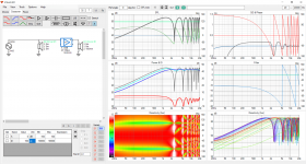
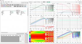
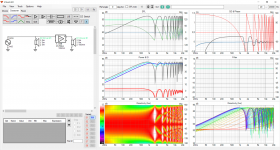
Increase delay further and there is more lows but the attenuation is worse, called subcardioid or something. Usable bandwidth stays about the same, there is always the "peak" below which the power just cancels out 6db per octave.
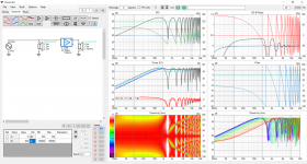
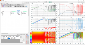
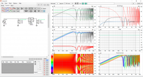
So, difference between dipole and cardioid is that the cardioid has some delay added to the "backside" signal. In reality "backside" can be provided from backside of single driver, or with another driver if both are boxed and approximate monopoles.
both dipole and cardioid are first order gradient systems, can be made from two monopoles. This is nice and quick experiment to do in VituixCAD since it has ideal monopoles available (driver with no data loaded to it).
One of the monopoles is inverted and some distance (d) between them and dipole pattern emerges, nulls to 90 degree off-axis below "dipole null" which happens when wavelength is d. Here d is 0.1m so null happens at 3430Hz.

If the other monopole is delayed the nulls start to turn to bigger angle than the 90 degrees and when delay equals d you have cardioid.


Increase delay further and there is more lows but the attenuation is worse, called subcardioid or something. Usable bandwidth stays about the same, there is always the "peak" below which the power just cancels out 6db per octave.


So, difference between dipole and cardioid is that the cardioid has some delay added to the "backside" signal. In reality "backside" can be provided from backside of single driver, or with another driver if both are boxed and approximate monopoles.
Last edited:
An active cardioid does have rear or side radiation that is how it works. An active or passive cardioid is trying to achieve the same thing, using delayed energy from the sides or rear to cancel out radiation from the front and create higher directivity. It is the cancellation of sound that limits the SPL in the cancellation range. An active cardioid is more flexible in that the cancellation range is easier to tune and can have more output as there is at least two or three drivers involved, but due to the cancellation there is always less SPL than if those drivers had been combined in an ordinary box style speaker on the front or within 1/4 wavelength of their operating frequency.So, why would an active cardioid (box speaker without rear radiation) not allow more LF output than a passive cardioid (open baffle in LF magnitude)?
Of course, but like I mentioned based on the numbers from the diffraction tool, a resistance enclosure with two woofers would lose by about 2dB at 100Hz compared to an active setup where the box is normal and the other woofer was used for cancellation.can have more output as there is at least two or three drivers involved, but due to the cancellation there is always less SPL than if those drivers had been combined in an ordinary box style speaker on the front or within 1/4 wavelength of their operating frequency.
Thanks for the patience btw 🙂
^Are you sure? I have understood it this way: The main frontside driver is the limiting driver always, and with dipole and cardioid back/side radiation (opposite phase) is cutting it's spl (efficency) no matter how the backside radiation is produced. Front driver's excursion is the limiting factor, and distortion might be a problem even before hitting Xmax.
Dipoles and cardioids can be "tuned" to have nulling freq higher or lower, and below this cancellation we loose 6dB/oct of spl. Only difference between dipole and cardioid is the radiation pattern.
If the construcion has sort of asymmetric/aperiodic feature, restricted radiation from the backside opposite phase or somehow modified spectrum of it, radiation pattern and total spl might be higher than an open system has. DSP and multiple drivers make this rather easy to accomplish. I haven't seen this kind of tests, but there might be some practical benefits with it. PA cardioid woofer systems are closely related.
http://musicanddesign.speakerdesign.net/VariabDF.html
https://toonz.ca/bose/wiki/index.php?title=Cardioid_Subs
https://blogs.qsc.com/live-sound/ho...-multiple-subwoofers-for-cardioid-deployment/
^^
thinkin out loud to check if we are following what you are at jaakkopetteri: Whats the difference if two drivers was used for passive cardioid in comparison if the same two drivers was used for active cardioid? And you see 2db difference in listening window response at 100Hz which is the question why is it 2db?
Main difference is that in the passive configuration both drivers contribute, doubled Sd.
Did you connect the drivers in series or parallel?🙂
Was your baffle different or same size on your experiments?
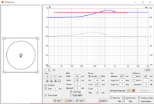
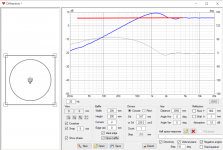
Example: closed box and OB / cardioid starts to deviate below bafflestep, roughly at 400Hz in this example. As you change baffles size difference at 100Hz would change. You could make difference at 100Hz to 0db or 6db or what ever.


I'm not sure at all 🙂^Are you sure? I have understood it this way: The main frontside driver is the limiting driver always, and with dipole and cardioid back/side radiation (opposite phase) is cutting it's spl (efficency) no matter how the backside radiation is produced. Front driver's excursion is the limiting factor, and distortion might be a problem even before hitting Xmax.
Indeed. To answer both of you: both methods cut SPL, but at low frequencies, the OB losses seem greater than the loss from using a woofer for cancellation rather than contribution. Intuitively, I would question whether the comparison is valid. Does a resistance enclosure really have the same exact losses as an OB?^^
thinkin out loud to check if we are following what you are at jaakkopetteri: Whats the difference if two drivers was used for passive cardioid in comparison if the same two drivers was used for active cardioid? And you see 2db difference in listening window response at 100Hz which is the question why is it 2db?
Yeah, I wasn't trying to generalize. I did mention "my case" which is 4" woofers on a 5.5" wide baffle, to be exactExample: closed box and OB / cardioid starts to deviate below bafflestep, roughly at 400Hz in this example. As you change baffles size difference at 100Hz would change. You could make difference at 100Hz to 0db or 6db or what ever.
The difference in your sims might come from different pathlength. Pathlenth can be fooled in dsp-actives be adjusting phase/delay difference.
The real world challenge is wide wavelength variation in music. Any dipole or cardioid construction works well only for 2-3 octaves.
The real world challenge is wide wavelength variation in music. Any dipole or cardioid construction works well only for 2-3 octaves.
Last edited:
Ideally yes, same losses, but perhaps you've constructed the system into reality so that there is some attenuation on the back, which would reduce cancellation. Also the introduced delay to get cardioid from dipole ought to increase bass on front due to the delay adding effective path length difference of the two monopoles towards listener.Indeed. To answer both of you: both methods cut SPL, but at low frequencies, the OB losses seem greater than the loss from using a woofer for cancellation rather than contribution. Intuitively, I would question whether the comparison is valid. Does a resistance enclosure really have the same exact losses as an OB?
ideal dipole
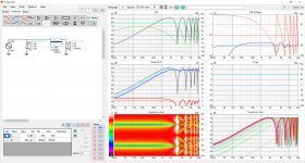
Ideal cardioid below. I'm using two ideal monopole drivers on this emulation/simulation, in reality the other driver could be driver on a box whose radiation is ~omni, or resistive vent(s) whose radiation is ~omni, for similar results. Added delay boosts the bass toward listener compared to dipole but at the same time the usable bandwidth brought down, it is limited on the top with the diffraction / interference that comes down as well with the delay so basically the usable bandwidth is still the same but now tad lower in frequency.
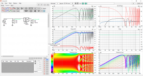
One could play with levels to affect the pattern, if backside is attenuated some the pattern is less good but more bass, less cancellation. In active configuration its easy to adjustments like this. Perhaps passive can do some attenuation as well with suitable damping material.
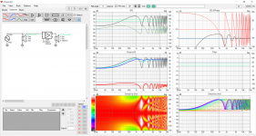
I'm curious where and how you get the data, are you emulating in VituixCAD? Dare to post screenshots? I'm not sure I understand what you are getting at?😀
Last edited:
No real simulations, just playing with the diffraction tool. Pic compares an open and a closed 5.5" wide baffle for an ideal 4" driver. If you then consider that a second woofer would add 6dB, the designs would cross around 150Hz, right? Below that, the open baffle "loss" is larger than the gain from a second wooferI'm curious where and how you get the data, are you emulating in VituixCAD? Dare to post screenshots? I'm not sure I understand what you are getting at?😀
Attachments
The Dutch&Dutch speaker is indeed very well made.
I however don't see why copying should be the best approach if you don't have the same design constraints.
The reason the port of the 8c is so close to the driver is because the chamber for that driver is very small.
If it were using a separate enclosure for the low end, then the port could possibly be situated further back - increasing the performance.
Am I too far off?
The back port needs to be at 1/4WL from the driver at the highest frequency of its operation, this means placement very close to the driver. If the port is further back then it will deviate from cardioid behaviour, hence decreased performance. This is what I understand, it would be nice if somebody confirms this point.
Hi, yeah idea is to match sound from front and back with small delay, and best opportunity is there right beside the driver. There is multiple things at play, probably all important things discussed in the thread at some point. If i remember results in this thread people have had success with different port positioning, sizing, materials..
So, probably multiple combinations of things work just fine. Best way is to make a prototype and adjust it until fine enough. Long day behind so no thought experiments 😀
So, probably multiple combinations of things work just fine. Best way is to make a prototype and adjust it until fine enough. Long day behind so no thought experiments 😀
The Dutch&Dutch speaker is indeed very well made.
I however don't see why copying should be the best approach if you don't have the same design constraints.
The reason the port of the 8c is so close to the driver is because the chamber for that driver is very small.
If it were using a separate enclosure for the low end, then the port could possibly be situated further back - increasing the performance.
Am I too far off?
It's quite complex, but the fundamental idea is that you can achieve a cardioid pattern over the span of about one octave.

This is why nearly all of the dipole and cardioid speakers are three-ways, four ways and even five-ways.
In my current project, titled "Nehalem", I found this out the hard way. Basically I made it a three way speaker and I thought that would be sufficient, but quickly learned that it probably needs to be a FOUR way or possibly even a FIVE way. It's a bit of a catch-22:
1) if you have sufficient displacement, you can basically get your woofers to play as low as you'd like. It's possible to get a fifteen or an eighteen to play down to 20Hz in a dipole or cardioid IF you're willing to sacrifice headroom
2) but realistically, we're accustomed to squeezing 105dB out of seven inch woofers, and when you start building cardioids and dipoles, it can be a bit shocking how much displacement you need to get a speaker to play down to 100hz, or even 150Hz really.
I started thinking, are there any successful active cardioid builds that have a single "ordinary" enclosure rather than multiple enclosures placed behind the other?
I've been playing around with VituixCAD using baffle simmed ideal drivers and also @vineethkumar01 's files for their 3-way build and I'm starting to feel like a decent cardioid pattern is really difficult to achieve with a canceling woofer mounted in the rear. Changing the distance between the drivers helps a bit, but not nearly enough. I can either achieve somewhat wideband cancellation at >120 degrees or between 45 and 90 degrees. I can't seem to do 45 to 180 degrees even for just one octave. Side-mounting the woofers solves the problem, so I'm guessing the rear half radiation on a rectangular enclosure is just too "chaotic" to control well, as @tmuikku mentions here https://www.diyaudio.com/community/threads/ikea-blanda-cardioid-ball-aka-gradient-1-4.392295/
I guess Kii Three is the only such commercial option and they indeed have side-mounted woofers. I wonder if even a spherical enclosure would suffice without side-firing woofers?
Hey there folks,
Here is my attempt on a passive cardioid.
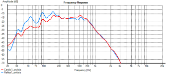
On the following graph is a comparison between two boxes of similar size using a 12" driver
The baffle is 35x35cm. Both are measured at same level and at the same place in the room.
Blue is a bass reflex, red is a passive cardioid.
As can be seen from the plot - the reflex has more output, but suffers more from the back wall reflections.
Here are the 0,30 and 60 degree measurements of both boxes.
So by comparison it's obvious that the concept works quite well.
Some tweaking is needed tho.
There is almost no cancellation at 150hz and a bunch of cancellation below 100 that I essentially don't need.
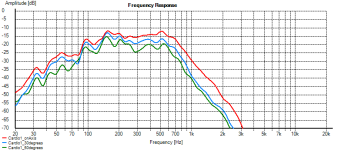
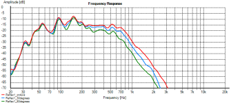
Any ideas what causes the pattern to collapse at a speciffic frequency?
And here is the DUT:
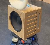
Here is my attempt on a passive cardioid.
On the following graph is a comparison between two boxes of similar size using a 12" driver
The baffle is 35x35cm. Both are measured at same level and at the same place in the room.
Blue is a bass reflex, red is a passive cardioid.
As can be seen from the plot - the reflex has more output, but suffers more from the back wall reflections.

Here are the 0,30 and 60 degree measurements of both boxes.
So by comparison it's obvious that the concept works quite well.
Some tweaking is needed tho.
There is almost no cancellation at 150hz and a bunch of cancellation below 100 that I essentially don't need.


Any ideas what causes the pattern to collapse at a speciffic frequency?
And here is the DUT:

- Home
- Loudspeakers
- Multi-Way
- Resistive port cardioid active speaker insipired by D&D 8C
