The frequency range of the cancellation depends on the time delay between the front and side signals. In a passive version that is from the position of the vents and the stuffing inside the enclosure. An active cardioid is easier to control, and it is relatively simple to have the pattern return to omni below 100Hz to not lose output but still have pattern control above that to help with SBIR problems.Any ideas what causes the pattern to collapse at a speciffic frequency?
Now that I think about it - the areas where the pattern collapses correspond to the peaks and dips of the frequency response.
I should get an outdoor measurement to be sure..
I should get an outdoor measurement to be sure..
Hi,
yeah the very low frequency data is not good if you measured inside, the room would affect and it would be better to measure outside ground plane.
Short guidance to help you imagine / visualize what happens with system like this:
There is no such thing as "no sound", like "there is no sound to the back with cardioid" kind of thought is too simple to get into whats happening. What actually happens is there is multiple sounds to the back and as they interfere its possible to get destructive or constructive interference, and the destructive interference makes the pattern, makes the frequency response plot look like there is no sound to the back. A cardioid pattern can be constructed with two ideal sound sources: one from the front of the cone, and the other from back of the cone, and the back was lowshelved (for bafflestep), delayed a bit and attenuated some, to get ideal pattern.
This in mind, in reality there is not two sounds only but they "generate" many interacting with the box: there is multiple apertures, then there is some reflections happening within the box, of course effect of the acoustic lowpasses and the damping material and so on. Outside of the box there is diffraction around the box and associated secondary sound sources forming at the edges, and these are happening to all sounds that output from the box. Result is there is multiple sounds with various path lengths and phase and magnitude coming toward a direction which ruins the ideal situation and the response we endup is something else than anticipated.
If we simplify a bit and think there was two sources only, from the front and from the back. Its entirely possible that at some angle and some frequency sound from the holes is louder than sound from the front and the pattern collapses. Or vice versa, sound from front is louder than from the back, and pattern collapses. Either of them has too much / little phase shift, and the pattern collapses. All because sound wavelength varies while the box size stays static and thus has different influence on sound at different wavelengths.
Takeaway for imagining interference is that loudest sound dominates, no matter where it originates, and the rest of the sounds that arrive mic within the IR window will either add or cut from that.
For example, if you measure at 150Hz from some off-axis angle and you estimate there should be certain attenuation but there isn't you need to figure out what are the sound sources toward that angle, path lengths to there, their phase and magnitude. This is so low a frequency you really need to get outside and do ground plane measurements 🙂 I suspect there is not much difference because the box looks much smaller than 150Hz wl, and you see nice downward slope. The above stuff mainly holds when sound wavelength is closer to the box dimensions.
Also as fluid posted above, its not possible to "reduce" cancellation for the lows with passive cardioid, all the bass is lost the minute there is hole in the box because the hole works as low pass filter and as wavelenght gets longer the lows always gonna have most cancellation. For this reason passive cardioid systems benefit from separate bass system, or very big total Sd, like open baffles, if you require more lows.
Last edited:
Thank you for the detailed explanation!
I'll do some more detailed measurements hopefully outdoors and also measure close to the port to see if there is some weird resonance.
I'll do some more detailed measurements hopefully outdoors and also measure close to the port to see if there is some weird resonance.
Sorry about poor english, can be hard to follow, wrote in a hurry 🙂 Yeah best way to get good results is tinker with it, have fun! 🙂
you may not be that far from a good result. Its hard to tell from what you presented. normalize your measurements and better yet take more measurements and all the way around. the speaker. The best I've seen (albeit in vituix simulation) is about 8 db attenuation off to the sides but as much as 20 db to the rear. If you are close to this you are good; else you need to play with the amount and kind of stuffing.
I think the colapse of cardioid pattern I was observing was due to the flor reflection.
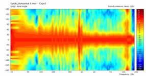
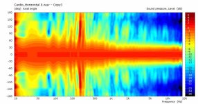
Here are some more measurements 0-180, at 10 degree increments.
On the first one the microphone is on the ground. On the second the mic is on the stand about 40cm above the ground.
Since I don't have a turntable that is very low, the speaker is also about 40cm off the ground.
On the first graph - the 800hz crossover is creating the pattern collapse, since the mic is vertically of axis enough.
On the second it's the floor bounce that does it.
I'm not even sure if the fuzzy region between 200 and 500 is some other reflections.
Will try to get some time at the local university's anechoic chamber and investigate further.
The only drawback I see with this design is the lack of loading on the driver.
Not sure if doing some funky front horn/slot cover and a double chamber in the back could load the driver a bit.
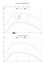
And here is a funky comparison between the 12" Cardioid box and an 18" Open Baffle driven by more or less the same output.
The interesting part is that the 12" has lower distortion for the same output.
I know this is not comparing apples to apples, but it's nevertheless interesting.
18OB - Blue
12Cardio -Red

Here are some more measurements 0-180, at 10 degree increments.
On the first one the microphone is on the ground. On the second the mic is on the stand about 40cm above the ground.
Since I don't have a turntable that is very low, the speaker is also about 40cm off the ground.
On the first graph - the 800hz crossover is creating the pattern collapse, since the mic is vertically of axis enough.
On the second it's the floor bounce that does it.
I'm not even sure if the fuzzy region between 200 and 500 is some other reflections.
Will try to get some time at the local university's anechoic chamber and investigate further.
The only drawback I see with this design is the lack of loading on the driver.
Not sure if doing some funky front horn/slot cover and a double chamber in the back could load the driver a bit.


And here is a funky comparison between the 12" Cardioid box and an 18" Open Baffle driven by more or less the same output.
The interesting part is that the 12" has lower distortion for the same output.
I know this is not comparing apples to apples, but it's nevertheless interesting.
18OB - Blue
12Cardio -Red
The Dutch&Dutch speaker is indeed very well made.
I however don't see why copying should be the best approach if you don't have the same design constraints.
The reason the port of the 8c is so close to the driver is because the chamber for that driver is very small.
If it were using a separate enclosure for the low end, then the port could possibly be situated further back - increasing the performance.
Am I too far off?
Kimmosto's comments gives confirmation you are not off imo.
https://web.archive.org/web/2021012...rdSub/CARDSUB.html#Hybridikardioidi_Alien2004
Thank you sharing all this.
Could you explain 'the lack of loading is the only drawback'? Isn't it the same for an OB?
Totally!Could you explain 'the lack of loading is the only drawback'? Isn't it the same for an OB?
I should do a comparison of just the 12" in free air vs in the leaky box.
It perhaps does give a bit of loading.
Kimmo's old page is a really interesting read!Kimmosto's comments gives confirmation you are not off imo.
https://web.archive.org/web/2021012...rdSub/CARDSUB.html#Hybridikardioidi_Alien2004
Thank you sharing all this.
Could you explain 'the lack of loading is the only drawback'? Isn't it the same for an OB?
I have always wondered why that was not given as prior-art in D&D's patent?
Kimmo's information was just open and public back in the day and most people were aware of his ideas and wonderful experiments.
The loading from a piston region point of view, is very similar to an OB that's correct.
It's basically just a open baffle with damping behind it.
Because of the acoustic resistance this would be a little better I guess.
This could be determined by measuring the drivers Qt in an open baffle situation and compare it with the Qt in the cardioid situation. An extremely simple impedance measurement can do this.
This would also show how linear it behaves.
It might also technically should give a correlation for the amount of resistance I think?
Although that doesn't really work for mid-low frequencies (say 250-500Hz)
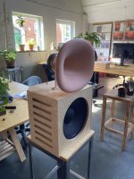
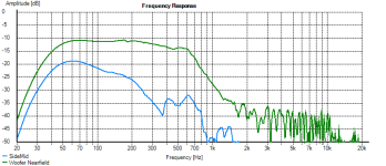
So here are some measurements I did today in small anechoic chamber (300hz).
This is the DUT and the crossover is 800hz.
The green trace is a nearfield measurement of the woofer.
The blue trace is a nearfield measurement of the ports.
Both are taken while the heavy cotton absorption was in.
I should try to see how a combination of the two would work.
I believe Geithain use some mix of absorptive materials or so they say in a press note.
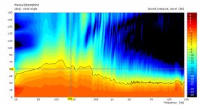
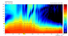
One measurement with poliester filling and one with heavier cotton absorption in the chamber.
The plot is normalized on axis and the black contour is the 6db curve.
It's a bit hard to see what the difference is apart from the Poliester filling
giving a bit smoother 6db contour, but more diffractionish marks in the HF region.
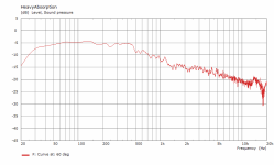
And the curve at 60 degrees for both again normalized to 0 degrees.
Not much to be seen 😀
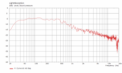
Subjectively - walking around the speaker it's obviously it's working.
In terms of the real in room benefits - I'm still looking forward to put it in a really bad room and find out.
This is the DUT and the crossover is 800hz.

The green trace is a nearfield measurement of the woofer.
The blue trace is a nearfield measurement of the ports.
Both are taken while the heavy cotton absorption was in.
I should try to see how a combination of the two would work.
I believe Geithain use some mix of absorptive materials or so they say in a press note.

One measurement with poliester filling and one with heavier cotton absorption in the chamber.
The plot is normalized on axis and the black contour is the 6db curve.
It's a bit hard to see what the difference is apart from the Poliester filling
giving a bit smoother 6db contour, but more diffractionish marks in the HF region.


And the curve at 60 degrees for both again normalized to 0 degrees.
Not much to be seen 😀


Subjectively - walking around the speaker it's obviously it's working.
In terms of the real in room benefits - I'm still looking forward to put it in a really bad room and find out.
Here are my 3d printed baffles for my D&D 8C clone. The finish will be a carbon foil.


Hi, yes I copied the 8c exactly but today I noticed the openings are 3cm too far back. I will change that. You can see measurements from 0 to 180 degrees in the appendix.
It looks like you live in a postcard! Very beautiful.
Wouldn't a light cone have lower distortion at lower spls and a heavy cone, less distortion at high splsThe interesting part is that the 12" has lower distortion for the same output.
Do anyone understand how what’s described in this patent differ from and what’s it’s advantage https://www.fulcrum-acoustic.com/wp-content/uploads/2019/10/Passive-Cardioid-Speakers-Explained.pdf
It’s also been explained on an a forum…”. The difference between an "aperiodic port" design and our passive cardioids is the acoustical mass of the ports and the amount of resistance. The acoustical mass in our passive cardioids puts a second-order low-pass filter a little below the frequency below which we want cardioid behavior. The resistance is just enough to damp the helmholtz resonance to "slightly underdamped" (Q of about 1). An aperiodic port design has almost no acoustical mass and is dominated by resistance, so there is essentially no helmholtz resonance and the resulting first-order low-pass corner is well above the passband; so it operates simply as a resistive leak that damps the sealed box resonance. If you look at the impedance of our passive cardioid subs, you'll see a trace of the double peaks of a ported box, but the dip between them doesn't go nearly as low. That's the effect of the port resistance.There is still significant reduction of excursion around the helmholtz frequency, and the summation of the rear radiation and front radiation increases the output over about 1 1/2 octaves. If you try to stretch the cardioid behavior beyond 1 1/2 octave, there will be a penalty in low frequency extension and maximum output
My take on it is I put in a Helmholtz tube tuned to the cabinet mode, and add resistance in it. But then isn’t this just a bass reflex with a foam plug? Or am I misunderstanding this completely.
Check out the attached pic of Fulcrum's subwoofer.
I think you can sim this using Hornresp.
Here's my hunch on what's going on:
1) In an aperiodic design, you are generally using a low density fill, and you're using a lot of it. Taken to the extreme, you can end up with an impedance curve that's approaching flat. It's frequency response will be close to a sealed box and there won't be a heck of a lot of output coming from the exit of the vent. So it's not going to very cardioid-ish, because there isn't much coming out of the vent. Similar to the B&W nautilus, but that's a closed transmission line.
2) In something like the Fulcrum design, it's a bit like a vented box, but the vent is stuffed with a high density fill. Because the fill has a high density, it acts a bit like a mass loaded transmission line. I don't know if the inside of the Fulcrum box is stuffed. Try modeling it in hornresp. If only the port is stuffed, you'll get something that's in a grey zone between a vented box and a cardioid. If you look at the published frequency response and impedance, you can see that the cardioid radiation is mostly at higher frequencies, and at low frequencies it's closer to a monopole.
Attachments
Recall that a cardioid is modelled in Vituix with a 2 driver model. The primary driver faces front; the secondary driver, which models the vents, can
face to the sides or to the rear, as would be the case here. The secondary driver is driven with a 2nd order low pass filter plus an L-pad. Fulcrum models the low pass filter as an air mass plus a resistance. This isn't different in principle than the acoustic low pass filters we get in our synergy mid ports.
Once you understand the physics (which I don't) you can build a spice simulation with electro-acoustic equivalents and tune the filter for optimal response, which then gets translated to the kind and amount of stuffing. Apparently, fairly light damping works best.
I think there are a couple of legacy AES papers on the subject that I haven't managed to get my hands on yet due to troubles on the AES website and a host of distractions.
They look very good. It would be interresting to see some measurements. How did you print them? Face down? Did you make your own waveguide for the tweeter?Here are my 3d printed baffles for my D&D 8C clone. The finish will be a carbon foil.
View attachment 1196904View attachment 1196905View attachment 1196906View attachment 1196907
- Home
- Loudspeakers
- Multi-Way
- Resistive port cardioid active speaker insipired by D&D 8C
