Just another baseless claim. For Marcel's dac we have all the information we need. For Andrea's dac we have your sales pitch.More strictly speaking, it cannot be literally true that 'nothing can be left to chance' by an engineering design made in this physical universe. To "leave nothing to chance" is an expression that most people know the meaning of. Same can be said for 'leave no stone unturned.' Andrea's dac contains no literal stones.
Assuming FIFO board uses FPGA or CPLD the generated output signals are not fully synchronous with MCK as FPGA/CPLD has propagation delays. Also isolators add their own propagation delay.Regarding the reclocker board I posted a pic of, think I said its an accessory board for the FIFO board. The FIFO board transmits signals synchronously so that metastability at the accessory board should never occur. It it does then there is a bad cable or something that needs troubleshooting.
In Marcel’s solid state Dac increasing the first stage’s gain by 6dB increased the measured distortion from below -120dB into the one digit PPM range. Way below being significant.Possibly, although such general rules should be tested in practice. Here is another comment on this.
Since the NRZ Firdac already measured a slightly higher distortion, but stil in the one digit ppm range, the difference might even hardly be measurable when increasing gain.
Hans
Thx for the linkHans,
You might try TheWellAudio.com
Mark
EDIT: Will send PM
Looking at all the different boards he is offering, it’s quite a busy chap.
And looking at his DSD board, it seems he is using a very long Firdac, with most likely different weight factors to relief the function of the reconstruction filter.
Hans
Attachments
Doesn't use different weight factors. I swapped hundreds of resistors to see how they sounded compared to the ones that came with the dac. Didn't find better ones, but found some considerably worse. Current/excess noise seems to be the main factor. Unfortunately, its not something usually specified for metal thin film resistors.
That I ordered so many resistors got Mouser thinking I was re-distributing parts, so they put my account in a restricted distributor category. Eventually got to the right person and sorted it out.
IIUC the long FIRDAC structure is mainly to desensitize the dac to clock doublers.
Anyway, if you study the pic carefully you can figure out quite a lot.
EDIT: Just occurred to me, found a common symptom of excess noise in thin film SMD resistors as used in Andrea's dac was blurred sound. IIRC Susumu RG was of the most blurry sounding. However, Susumu does make an RS series for hi-fi audio use, but nobody had them in stock in tight enough tolerances.
Last edited:
Hans,
Maximum RTZ DSD sample rate is a function of clock frequency. It might be able to do RTZ with DSD512 using 45/49MHz clocks, not sure. But clock phase noise gets worse up there. So far listening tests that have been done show subjective preference for lower phase noise.
Mark
Maximum RTZ DSD sample rate is a function of clock frequency. It might be able to do RTZ with DSD512 using 45/49MHz clocks, not sure. But clock phase noise gets worse up there. So far listening tests that have been done show subjective preference for lower phase noise.
Mark
Last edited:
H
Hans
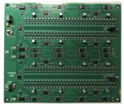
Instead of the 8 resistor output of Marcel’s Firdac, I count 32 resistors, so the first sinc zero will be 4 times lower, potentially resulting in a simpler less demanding analog reconstruction filter.Doesn't use different weight factors. I swapped hundreds of resistors to see how they sounded compared to the ones that came with the dac. Didn't find better ones, but found some considerably worse. Current/excess noise seems to be the main factor. Unfortunately, its not something usually specified for metal thin film resistors.
That I ordered so many resistors got Mouser thinking I was re-distributing parts, so they put my account in a restricted distributor category. Eventually got to the right person and sorted it out.
IIUC the long FIRDAC structure is mainly to desensitize the dac to clock doublers.
Anyway, if you study the pic carefully you can figure out quite a lot.
EDIT: Just occurred to me, found a common symptom of excess noise in thin film SMD resistors as used in Andrea's dac was blurred sound. IIRC Susumu RG was of the most blurry sounding. However, Susumu does make an RS series for hi-fi audio use, but nobody had them in stock in tight enough tolerances.
Hans
A quick note in case anyone is concerned: The reclocker board that will be used with Marcel's dac was designed and tested with the FIFO board to make sure metastability would not be a problem. Use of two flip-flops was considered but measurements showed it increased crosstalk and that it did not provide any practical benefit in this application. As I wrote earlier with some literary license, one design philosophy was to leave no stone unturned. I will leave it at that.
H
Instead of the 8 resistor output of Marcel’s Firdac, I count 32 resistors, so the first sinc zero will be 4 times lower, potentially resulting in a simpler less demanding analog reconstruction filter.
Hans
It could also be eight times lower. My FIRDAC has four taps with (ideally) half bit clock cycle delays between them and with equal weights, so uniform weighting over two bit clock cycles. See post #1342 for an explanation why I use so many flip-flops and resistors per tap.

About double flip-flop synchronizers: when the first flip-flop gets metastable, you get 1 clock cycle peak-peak timing uncertainty. You definitely don't want that on the bit clock, so you would need to find a way to get rid of it again. Anyway, not applicable when there is no timing issue anyway.
Marcel,
I never looked in detail to U14 and U16,
but now that I did I have an understanding problem.
The same signals clocked into U16 in D1, D3, D5 and D7 are at the same time also clocked into U14 in D0, D2, D4 and D6, contributing at the output in both cases as the same 4 bit summed total, say Sum1.
Exactly the same happens into U16 in D0, D2, D4 and D6 being equal to U14 in D1, D3, D5 and D7 in both cases again contributing at the outputs in the other 4 bit equal summed total say Sum2.
The summed 8 bit outputs of U14 and U16 now become in both cases Sum1+Sum2, so completely identical instead of complementary.
What do I overlook ?
Hans
Look carefully how the resistors are connected. The eight outputs of U14 are not summed. The resistors average or sum (depending on how you look at it, in Thevenin voltage or Norton current) four outputs of U14 with four of U16.
The noninverted data with zeros in between are shifted to the even outputs of U14 and the odd outputs of U16, and then averaged/summed with eight resistors.
The inverted data with zeros in between are shifted to the odd outputs of U14 and the even outputs of U16, and then averaged/summed with eight resistors.
These averages/sums are therefore in antiphase.The filter takes their difference.
Last edited:
Re: testing, at least two members here reported better results with passive filters/transformer output stages of this DAC. Perhaps you could also measure/test this as well…Mark,
Reading Andrea’s board specs, in RTZ mode the maximum rate is DSD256 so this will also be your maximum test rate.
Not a real problem, but some people may prefer that DSD512 also be tested.
Hans
Not really possible with the current measurement system but I was more interested in the distortion figures to compare with the electronic output stage. The setup for this test looks fairly simple, some caps and then connect to readily available transformers like Lundhal, etc.
Btw, I note that your custom transformer has less than 50k BW and yet sounds so good at DS256. Possibly even better if the BW of the Trafos can be higher…to take advantage of DSD256 noise distribution
Btw, I note that your custom transformer has less than 50k BW and yet sounds so good at DS256. Possibly even better if the BW of the Trafos can be higher…to take advantage of DSD256 noise distribution
Last edited:
- Home
- Source & Line
- Digital Line Level
- Return-to-zero shift register FIRDAC