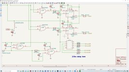
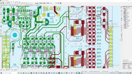
@MarcelvdG : Hi ... Back from my short vacation and now playing around with your fine RTZ FIRDAC and its layout. In this context a couple of questions pop up that I hope you may be able to just briefly help with (I have attached screendumps of the PCB XOR -> LV574 clock connections, and a slightly modified schematic, please see below):
1. When looking at your layout for the DAC itself (I think it should be the latest/only version ... ) I can see that you use 0.375mm and 0.15mm trace widths for the connections from the XOR (clock doubler, U28A) to the LV574s, and also a non-series resistor 0.25mm trace going to U22, U24, U26 and U27. I also notice in post #1 that the PCB should be designed for 0.21mm 7628 prepreg.
If I use Saturn PCB design tool to assess the impedances of these traces I get:
I am not a trace impedance expert but I would have imagined that the impedances ideally were to be identical, i.e. that the parallel connection of the 72.5 ohms impedances (~36.2 ohms) would have been the same as the 48.3 ohms impedance - and the 59 ohms (?) ... Also, won't the parallel connection of these three branches out from the XOR clock doubler load the XOR with a quite low impedance (assumed like ~59ohms//~48 ohms ~ 26.5 ohms)? I may be missing something here - but given bohrok2610's finding that your fine DAC improves considerably with a low phase noise signal I am just reviewing this part ...
2. Alternatively, I am considering placing a clock buffer (NB3L553, 2.5ns Tpd at 5VDC, https://www.onsemi.com/pdf/datasheet/nb3l553-d.pdf ) after pin 7 of U28A (tentative schematic attached). I would then connect pin 7 of U28A to the U22->U27 direct trace - and also directly to the CLK input on the NB3L553. Each of the outputs from the NB3L553 would then be led to either of the LV574s ...
I assume the main issue with this is that the clock buffer will add ~2.5 ns of delay relative to the outputs of the U22->U27s. Not knowing the exact timings of your circuitry I wonder if this would work out?
And then slightly off-topic: I have never ordered from JLCPCB before and I don't seem to find specifications on minimum trace to copper pour clearance nor minimum trace width. Might one of you know of this?
Cheers & thanks for considering,
Jesper
1. When looking at your layout for the DAC itself (I think it should be the latest/only version ... ) I can see that you use 0.375mm and 0.15mm trace widths for the connections from the XOR (clock doubler, U28A) to the LV574s, and also a non-series resistor 0.25mm trace going to U22, U24, U26 and U27. I also notice in post #1 that the PCB should be designed for 0.21mm 7628 prepreg.
If I use Saturn PCB design tool to assess the impedances of these traces I get:
- 48.3 ohms for the traces going from R132/R133 to the trace split,
- 72.5 ohms for the traces splitting from the above trace and then continuing to the LV574s,
- and 59 ohms for the trace going directly to the U22 -> U28.
I am not a trace impedance expert but I would have imagined that the impedances ideally were to be identical, i.e. that the parallel connection of the 72.5 ohms impedances (~36.2 ohms) would have been the same as the 48.3 ohms impedance - and the 59 ohms (?) ... Also, won't the parallel connection of these three branches out from the XOR clock doubler load the XOR with a quite low impedance (assumed like ~59ohms//~48 ohms ~ 26.5 ohms)? I may be missing something here - but given bohrok2610's finding that your fine DAC improves considerably with a low phase noise signal I am just reviewing this part ...
2. Alternatively, I am considering placing a clock buffer (NB3L553, 2.5ns Tpd at 5VDC, https://www.onsemi.com/pdf/datasheet/nb3l553-d.pdf ) after pin 7 of U28A (tentative schematic attached). I would then connect pin 7 of U28A to the U22->U27 direct trace - and also directly to the CLK input on the NB3L553. Each of the outputs from the NB3L553 would then be led to either of the LV574s ...
I assume the main issue with this is that the clock buffer will add ~2.5 ns of delay relative to the outputs of the U22->U27s. Not knowing the exact timings of your circuitry I wonder if this would work out?
And then slightly off-topic: I have never ordered from JLCPCB before and I don't seem to find specifications on minimum trace to copper pour clearance nor minimum trace width. Might one of you know of this?
Cheers & thanks for considering,
Jesper
Attachments
") - I had missed that.
- I had missed that.Some new information to report. Metal foil resistors have been installed, except one at R44. Lost one in handling and couldn't find it after a prolonged search. Replaced it with one of the original metal film resistors. Since I am listening in SE mode and the resistor substitution is in the negative phase, it is not expected to affect listening impressions at this juncture. Dac was allowed to settle in overnight. So far I am the only one to have heard it so what I report about sound changes is very preliminary.
My initial impression is there the sound has changed, but for some purposes only slightly. I think I can hear a little deeper into the music and there may be a little less distortion/noise. However, the system here is capable of making the 16-bit truncation/dither floor audible (although it sounds different on different recordings, possibly due to the particular dither algorithm; adaptive noise-shaped dither usually sounds better here as compared to TPDF). The electrostatic motor speakers here tend to help make low level details more easily audible, if it helps to know the context. Anyway, seems to me there is not much difference with most 16/44 source material, although I think there is a little bit of improvement there. OTOH, with well recorded hi res recordings, the increased openness and increased low level detail is more noticeable and easier to appreciate.
For example, listening to Vivaldi Cantata Rv679 - Che Giova Il Sospirar, Povero Core - Aria - Cupido, Tu Vedi (from this album: https://www.nativedsd.com/product/2l056-bellezza-crudel-vivaldi/ ), upsampled to DSD256 by PCM-DSD software converter, best as I can recall, don't think I have ever heard it sound any more realistic on any dac than it does now with the new resistors.
Last edited:
A couple of other people have stopped by to listen. General consensus is that it sounds better, more clear, less haze. One person commented the dac still needs more work in other areas, but it sounds the best it has so far. Consensus is also that the improvement in sound is probably not worth the increased cost. Also, maybe best to try to perfect the rest of the to and see how good it can get. Then at that point if someone wants a 'best you can do, cost is no object' dac, then maybe add the resistors as the final upgrade.
My side comment: Maybe still worth trying to drive the RTZ function from clocked logic. Need another board from Andrea for that. Will check on when the next shipment from Italy is likely to happen. Once that is out of the way, about all that would be left to look at would be more on Vref and or output stage and filtering.
My side comment: Maybe still worth trying to drive the RTZ function from clocked logic. Need another board from Andrea for that. Will check on when the next shipment from Italy is likely to happen. Once that is out of the way, about all that would be left to look at would be more on Vref and or output stage and filtering.
@MarcelvdG : Hi ... Back from my short vacation and now playing around with your fine RTZ FIRDAC and its layout. In this context a couple of questions pop up that I hope you may be able to just briefly help with (I have attached screendumps of the PCB XOR -> LV574 clock connections, and a slightly modified schematic, please see below):
1. When looking at your layout for the DAC itself (I think it should be the latest/only version ... ) I can see that you use 0.375mm and 0.15mm trace widths for the connections from the XOR (clock doubler, U28A) to the LV574s, and also a non-series resistor 0.25mm trace going to U22, U24, U26 and U27. I also notice in post #1 that the PCB should be designed for 0.21mm 7628 prepreg.
If I use Saturn PCB design tool to assess the impedances of these traces I get:
- 48.3 ohms for the traces going from R132/R133 to the trace split,
- 72.5 ohms for the traces splitting from the above trace and then continuing to the LV574s,
- and 59 ohms for the trace going directly to the U22 -> U28.
I am not a trace impedance expert but I would have imagined that the impedances ideally were to be identical, i.e. that the parallel connection of the 72.5 ohms impedances (~36.2 ohms) would have been the same as the 48.3 ohms impedance - and the 59 ohms (?) ... Also, won't the parallel connection of these three branches out from the XOR clock doubler load the XOR with a quite low impedance (assumed like ~59ohms//~48 ohms ~ 26.5 ohms)? I may be missing something here - but given bohrok2610's finding that your fine DAC improves considerably with a low phase noise signal I am just reviewing this part ...
2. Alternatively, I am considering placing a clock buffer (NB3L553, 2.5ns Tpd at 5VDC, https://www.onsemi.com/pdf/datasheet/nb3l553-d.pdf ) after pin 7 of U28A (tentative schematic attached). I would then connect pin 7 of U28A to the U22->U27 direct trace - and also directly to the CLK input on the NB3L553. Each of the outputs from the NB3L553 would then be led to either of the LV574s ...
I assume the main issue with this is that the clock buffer will add ~2.5 ns of delay relative to the outputs of the U22->U27s. Not knowing the exact timings of your circuitry I wonder if this would work out?
And then slightly off-topic: I have never ordered from JLCPCB before and I don't seem to find specifications on minimum trace to copper pour clearance nor minimum trace width. Might one of you know of this?
Cheers & thanks for considering,
Jesper
Hi Jesper,
Apologies for the slow reply. It has been an exhausting week for me for reasons that are political and are therefore strictly forbidden on this forum.
You are right that the trace impedances have become a bit messy. I think I started with the Eurocircuits default prepreg thickness (360 um PR7628) and trying to avoid traces narrower than 0.25 mm. Then later the whole thing was ported to thinner prepreg and a minimum trace width of 0.15 mm. I left the traces that were not terminated anyway (the ones I assumed to be electrically short) at their original width and only adjusted the terminated ones.
The doubled clock traces were supposed to be 50 ohm and then split into two 100 ohm lines, but I couldn't make the 100 ohm lines because of the trace width constraints (neither with 360 um and 0.25 mm nor with 210 um and 0.15 mm). Widening up the first part of the line would have made the loading on the EXOR gate even worse, so I just left it as it is now.
In principle, a trace with a characteristic impedance Z0, an input series termination resistor with a value equal to Z0 and a high-impedance load at the other side presents a load of 2Z0 to the driving gate until the signal has reflected and travelled back to the driving gate. After that, the current is supposed to go to 0. (In fact, I usually use series termination resistors that are a bit smaller than Z0 because of the output resistance of the logic gate itself.) Electrically short lines can be treated as lumped capacitors as long as their far ends are open or loaded by something with a high impedance.
Regarding the clock buffer, Markw4 has shown that the hold time for the 74LV574A is marginal already, so I expect the 2.5 ns extra will not be acceptable. You can solve that by delaying the data with an RC network, or possibly by just increasing the values of R129, R131 and their colleagues of the right channel, and using the trace and 74LV574A input capacitance.
Thank you for your efforts and all noted, At least there is one more interesting reference ( the other from TC )Some new information to report. Metal foil resistors have been installed, except one at R44. Lost one in handling and couldn't find it after a prolonged search. Replaced it with one of the original metal film resistors. Since I am listening in SE mode and the resistor substitution is in the negative phase, it is not expected to affect listening impressions at this juncture. Dac was allowed to settle in overnight. So far I am the only one to have heard it so what I report about sound changes is very preliminary.
My initial impression is there the sound has changed, but for some purposes only slightly. I think I can hear a little deeper into the music and there may be a little less distortion/noise. However, the system here is capable of making the 16-bit truncation/dither floor audible (although it sounds different on different recordings, possibly due to the particular dither algorithm; adaptive noise-shaped dither usually sounds better here as compared to TPDF). The electrostatic motor speakers here tend to help make low level details more easily audible, if it helps to know the context. Anyway, seems to me there is not much difference with most 16/44 source material, although I think there is a little bit of improvement there. OTOH, with well recorded hi res recordings, the increased openness and increased low level detail is more noticeable and easier to appreciate.
For example, listening to Vivaldi Cantata Rv679 - Che Giova Il Sospirar, Povero Core - Aria - Cupido, Tu Vedi (from this album: https://www.nativedsd.com/product/2l056-bellezza-crudel-vivaldi/ ), upsampled to DSD256 by PCM-DSD software converter, best as I can recall, don't think I have ever heard it sound any more realistic on any dac than it does now with the new resistors.
Acko, IME it really depends on the particular resistors. Some, such as Susumu RG, sounded pretty bad to me for this particular type of application. The resistors Marcel called out in the BOM (or else the ones used to build the version of the dac here, if different from the BOM) happen to sound pretty good. That said, I'm liking the sound of the dac a lot with the new resistors even though I know some other changes to the dac might help the overall sound too. Maybe the opamp Vref supply could be supplanted with something public domain such as a discrete Nazar regulator. Or maybe a shunt.
https://s-audio.systems/blog/nazar-regulator/?lang=en
http://designideas.cocolog-nifty.com/blog/2015/08/psu-for-high-en.html (Chrome browser with translation enabled may be useful for this site)
https://s-audio.systems/blog/nazar-regulator/?lang=en
http://designideas.cocolog-nifty.com/blog/2015/08/psu-for-high-en.html (Chrome browser with translation enabled may be useful for this site)
Last edited:
I was actually surprised by your experience with this Susumu RG version despite all the promoted benefits - Maybe something in the switching action that affected the properties.
other improvements could be considered but for Vref I thought this bandgap ref on the board was the best but looks like others like LT3042 type ref better. Nazar ones look good but where can we buy samples for evaluation? Shunts may not like the large ceramic caps on board so it is going to be tricky?
Anyway, I think we need to wrap up things and review plans going forward. Marcel’s design has proven itself and many will benefit from this implementation.
Mark, I haven't really followed this thread closely butAcko, IME it really depends on the particular resistors. Some, such as Susumu RG, sounded pretty bad to me for this particular type of application. The resistors Marcel called out in the BOM (or else the ones used to build the version of the dac here, if different from the BOM) happen to sound pretty good. That said, I'm liking the sound of the dac a lot with the new resistors even though I know some other changes to the dac might help the overall sound too. Maybe the opamp Vref supply could be supplanted with something public domain such as a discrete Nazar regulator. Or maybe a shunt.
https://s-audio.systems/blog/nazar-regulator/?lang=en
http://designideas.cocolog-nifty.com/blog/2015/08/psu-for-high-en.html (Chrome browser with translation enabled may be useful for this site)
WRT DAC, is this a voltage out arrangement that you are feeding in to the transformer?
WRT Regs, Nazar style reg is IME capable of very high performance, I've designed and built many versions. It's worth just doing your own, start with Ltspice and go from there.
You ready for me to send it back? If so, I'm okay with that....we need to wrap up things...
Marcel, any thoughts on your part?
Link to schematic is in the first post, I believe. Only mod at the moment is a 120R, 1/2W metal film in parallel with each 22uf X5R in the Vref supplies. Not using the filter board at the moment, only the dac board fed through u.fl connectors. Dac output has DC offset which is DC blocked by an electrolytic and an MKP in parallel. BLCK and data signals come from Andrea Mori reclocker board located very close to Marcel's dac, reclocker board in turn is fed from an Andrea Mori FIFO buffer board. Clocks are SOA Acko Labs AKX-22. PCM->DSD most often provided by the forum's FPGA-based Simple DSD Converter project running version 3 firmware.WRT DAC, is this a voltage out arrangement that you are feeding in to the transformer?
Last edited:
@Terry Demol, are you able to help out with the design of a well tuned unit to match this DAC? Thank youMark, I haven't really followed this thread closely but
WRT DAC, is this a voltage out arrangement that you are feeding in to the transformer?
WRT Regs, Nazar style reg is IME capable of very high performance, I've designed and built many versions. It's worth just doing your own, start with Ltspice and go from there.
Maybe the opamp Vref supply could be supplanted with something public domain such as a discrete Nazar regulator. Or maybe a shunt.
https://s-audio.systems/blog/nazar-regulator/?lang=en
http://designideas.cocolog-nifty.com/blog/2015/08/psu-for-high-en.html (Chrome browser with translation enabled may be useful for this site)
Those circuits use an LM317 or LT317A as a reference, with a low-pass filter to get rid of the noise. That is likely to result in more deep subsonic noise than the original reference regulator and therefore in stronger very-close-in amplitude noise sidebands around the signal. Same kind of effect on the signal as excess noise in the DAC resistors, although I don't know which will dominate.
- Home
- Source & Line
- Digital Line Level
- Return-to-zero shift register FIRDAC