I have no idea whether this will solve the 10 kHz distortion issue (to the extent that there is an issue at all, the distortion bohrok2610 measured at 10 kHz is larger than at 1 kHz, but not excessively large).
If the distortion results from non-ideal behaviour of the common mode servo, yes.
You will also experience reduced noise and a single ended output from either polarity output that has rejected the common mode noise from the source.
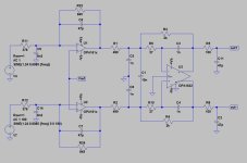
The "asymmetry" is an illusion. As long as the Op-Amp's are sufficiently fast for the audio signal in the closed loop the circuit behaves completely symmetric. in electrical terms. If set up as dual Op-Amp this extends to power rails.
The second Op-Amp operates at a gain of -1 and creates an inverted copy of the main output signal.
So if we look at this "black box" we have two opposite polarity inputs, two opposite polarity outputs and one Vcom input pin.
The outputs are not 100% symmetric at (very) high frequencies, but that depends on the second Op-Amp. With an 85kHz turnover frequency integrator and 18MHz GBWP I'm not really worried.
Thor
The "stock" filter is exactly the same as Marcel's first 2 filter stages. Only difference is layout and passive component selection. Opamps are the same as in Marcel's. My dac uses the PCM2DSD converter so input is DSD256. Since the distortion is low without the CM loop my assumption is that the problem is with CM loop opamp. Maybe it is too "slow" as JosephK suggested. I have also made slight variations to the CM loop passive components making the loop "faster" or "slower". These changes also impact differential distortion (albeit only slightly) which further points to CM loop being the issue.So the question is: how can these large differences be explained. When I remember correctly, in my case the filter was equiped with the OPA2210, what amps did you use ?
And does the used DSD frequency make a difference for the 10Khz distortion that you measured, I made my measurement at DSD256.
Is there a reason why this relatively bog-standard output stage would not work with RTZ?
Non I can see.
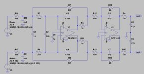
But why not swap the I/U conversion to OPA1632? And you might want to increase capacitor values in the I/U conversion feedback loop.
One of the downsides of using OTS FDA's can be noise performance in SE mode, due to relatively common mode noise levels from the common mode feedback loop, which is why I prefer the Birt circuit.
Thor
Marcel’s Firdac is certainly a very interesting option to build, but I found Marcel’s solid state Dac at least as interesting and in basic form even better sounding while also using the same Firdac principle.
I’m probably one of the few who had the opportunity to audition both.
The big difference though is that you won’t need an Amanero or whatever conversion tool to generate Raw DSD.
And you won’t have to convert your PCM files into DSF either, a proces that is not lossless and you can drive the Dac over s/pdif.
And just like the Firdac, Marcel’s solid state Dac has certainly possibilities for even further optimizing the sound.
The only drawback is that this solution is a more expensive and that the used FPGA might be difficult to obtain.
Hans
Unfortunately the Trenz FPGA module has prohibitive cost. That alone costs more than all parts (chassis included) to my RTZ build.The only drawback is that this solution is a more expensive and that the used FPGA might be difficult to obtain.
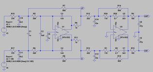
This filter has very similar characteristics as stock filter.
Looks right.
You could try LT1028/1115 in the first stage Birt style, any good, fast and low noise CFB OPA as inverter. Maybe THS6012/TPA6120 as inverter?
Second stage maybe OPA1656?
Just saying....
Thor
So isn’t it about time that Marcel should update this perfect design with a more affordable FPGAUnfortunately the Trenz FPGA module has prohibitive cost. That alone costs more than all parts (chassis included) to my RTZ build.

Hans
You seem more mellow these days ;-)
Not really, just no time to make sure what is right...
- very sweet daughter!
Daughter?
Thor
Forgetting about the hundreds of possible alternative filter topologies for a moment, does anyone understand why the common-mode loop of the original filter has a substantial influence on the differential distortion? If so, why only on the 10 kHz harmonic distortion and not on Hans's intermodulation distortion measurement?
And just like the Firdac, Marcel’s solid state Dac has certainly possibilities for even further optimizing the sound.
The only drawback is that this solution is a more expensive and that the used FPGA might be difficult to obtain.
Hans
There are 4 in stock now, of a newer version:
https://shop.trenz-electronic.de/de...LX45-2I-128-MByte-DDR3L-Mini-USB-2.0-4-x-5-cm
The noise floor on Hans's IMD measurement is about 20 dB higher than on mine so it hides most of the stuff seen on my measurement.Forgetting about the hundreds of possible alternative filter topologies for a moment, does anyone understand why the common-mode loop of the original filter has a substantial influence on the differential distortion? If so, why only on the 10 kHz harmonic distortion and not on Hans's intermodulation distortion measurement?
And regarding the level on my measurement since CCIF IMD is 1:1 ratio clipping starts at -3dBFS. It is not possible to use 0dBFS level.
As I said earlier at least in simulation the CM suppression of stock filter is not perfect. Could it be that HF CM noise/distortion results in differential mode noise/distortion elsewhere in the filter?
Last edited:
Yes your noise level is 20dB lower, because you are probably using a bin width that’s 1/100 of the one that I used.
But nevertheles the more important IMD products in the one digit ppm range are clearly visible with some 20dB above the noise.
I used the 19 & 20Khz tones at -6db each, giving a level at 0dBFs peak and on average -3dBFs.
That seems to correspond with your findings.
Would be nice to see your spectrum at this maximum level to compare with mine.
Hans
- Home
- Source & Line
- Digital Line Level
- Return-to-zero shift register FIRDAC