In the past - not math savvy - I have just taken a square wave, a pot (10k for instance also for undefined 1:1 transformers that might be 600Ω) plus a pot and a small cap, turning and adjusting and fitting values untill the square wave is flat. No ringing.
But that is not to the ear. A little bit less might be better. Flat might be dull.
But that is not to the ear. A little bit less might be better. Flat might be dull.
So, let us see if I did my math/learning exercise correctly. Looking back at the schematics now knowing which resistors are in play at setting input impedance with some math it is clear they are all in parallel. Going back to all 4 schematics with that assumption the input impedance for all 4 is roughly 100K.Marauder R3//R6
Nimitz R1//R4//R5
Hornet R1//R5//R6
Bon Home - depends of module used
So, I left the R1/R3 (R7 in Bon Homme) bleeding resistor values alone and played with the appropriate R4/5/6 (or R13/14 in Bon Homme) and came up with new values that got me to ~18K input impedance (if I did it correctly).
Marauder R3 1Meg, R6 18K
Nimitz R1 330K, R4 and R5 each 40K
Hornet R1 1Meg, R5 and R6 each 36.5K
Bon Homme R7 1Meg, R13 51.8K and R14 28.7K which maintains the 1.8/1 ratio of R13 to R14.
Now if my homework is correct the next question becomes do these new values effect Mark's circuits?
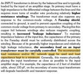
Be sure to read the application notes by Bill Whitlock, on the Jensen Transformers website. They talk about the Jensen philosophy (or call it stiff necked orthodoxy if you wish), for choosing the optimum loading network / Zobel network across the transformer secondary. But of course D.I.Y. means do it your way -- not necessarily Bill Whitlock's way.
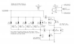
You'll see that the Front Ends with an output transformer, use a secondary termination with one R and one C ... unlike the attached figure below.
_
I hit the Jensen website tonight and did some reading on Bill's take on balanced to unbalanced conversions. I came across this excerpt from https://www.jensen-transformers.com/wp-content/uploads/2014/08/an002.pdf Highlighted section seems to cover Cinemag's view, make sure input impedance is optimal, and also Jensen's view that it may be better to add an RC network. At this point even doing some studying I would still have to defer to the knowledge here is just matching the input impedance is enough.
Attachments
Last edited:
Hey @CoGT3, I have extra Nimitz and Bon Homme boards that I would be happy to send you. That way you can order some of the other front ends that interest you. Send me a message if you are interested.So, I also grabbed some of the 2SJ18s. Had only planned to build the Tokin OS when available but couldn't pass up trying this OS with some real Sony VFETs. I already have the VFET chassis from the preorder so now its time to commit to some FE boards and place an order with the pcb fabs. Already have decided to do Nimitz, Hornet, and Bon Homme Richard. Real question is which of the transformerless FE boards to try. I have tried the search function and their seem to be some people that have done both Dreadnaught and Marauder. Haven't seen any comments comparing one to the other. Haven't seen any comment about Lexington yet. Anyone out there that built Marauder or Dreadnaught see something in Lexington that has them itching to give it a try? My bias for no good reason is to try Marauder based on the fact the store has boards and parts ready, and there seems to be the most comments about Marauder. But I am open to persuasion toward the others.
......
Marauder R3 1Meg, R6 18K
Nimitz R1 330K, R4 and R5 each 40K
Hornet R1 1Meg, R5 and R6 each 36.5K
Bon Homme R7 1Meg, R13 51.8K and R14 28.7K which maintains the 1.8/1 ratio of R13 to R14.
.......
something is fishy with your calc and I did check just Marauder, you do the rest
parallel connection is 1/R= 1/R1+1/R2+.....1/Rn
so , for marauder that's 1/R=1/1Meg+1/100K = 90K909
..............ok, first morning coffee, so why not all
Nimitz 1/R=1/330K+1/330K+1/330K , for that I don't even need calculator - that's 110K
Hornet 1/R=1/1Meg+1/100K+1/100K=47K62
Bon Homme R7 in parallel to whatever figures on preamp module
Did math yesterday morning after first coffee, didn't post till last night after reading Bill Whitlock's articles well after first coffee had worn off. Clearly forgot Hornet was 1/2 the input impedance of the others. I reattached Bon Homme, the preamp section is on the second page, but basically shows a 270K up and 150K down resistor with same 1Meg bleeding resistor, works out to 87K947. Considered ~90K and 110K close enough to 100K to confirm everything is parallel.
Just finished morning coffee today and reran my new R values, all in the 18K ballpark. Tweaked some values based on available resistor sizes and seems close enough to 18K. Of course this goes out the door if there is some unforeseen effect of changing the R to the rest of the FE circuit.
Just finished morning coffee today and reran my new R values, all in the 18K ballpark. Tweaked some values based on available resistor sizes and seems close enough to 18K. Of course this goes out the door if there is some unforeseen effect of changing the R to the rest of the FE circuit.
Attachments
I'm not following you with "18K" figure at all, but maybe that's something you want to change to, you'll manage following explained logic
anyhow, if you want to change something, best to ask designer which way is the best
Bon Homme , silly me, didn't saw page 2
anyway, its Rin is R7//R13//R14
anyhow, if you want to change something, best to ask designer which way is the best
Bon Homme , silly me, didn't saw page 2
anyway, its Rin is R7//R13//R14
So the 18K thing...
Proposed signal pathway: PL XP22 XLR out-5m balanced cable-XLR input on amp chassis-Cinemage line transformer-SE input of FE boards.
Plan: mount Cinemag 15/15B line transformer in chassis with primary wire to XLR input and secondary directly wire to SE input of FE boards.
Potential problem: Per Cinemag line transformer wants to see 18K impedance load for secondary for phase coherence and most linear frequency response, FE boards discussed above vary from 50K-110K input impedance.
Proposed solution: Play with values of R on FE boards to change input impedance to 18K to make Cinemag secondary happy.
Questions to be answered: Do these changes have an ill effect on Mark's FE boards? I agree, he is best to answer.
Sidebar: Mark has suggested that Bill Whitlock at Jensen would not just load secondary with R but likely an RC network. Don't know near enough to dispute that, was just following Cinemag's suggestion of altering input R to 18K if possible.
Feel free to modify your own set of Front End cards however you like! The avant-garde, woo woo contingent may have some advice to offer about resistor choices, such as magnetic (ferrous) vs non-magnetic leads, mil-spec vs industrial, film vs foil, specific manufacturer, etc.
So the 18K thing...
Proposed signal pathway: PL XP22 XLR out-5m balanced cable-XLR input on amp chassis-Cinemage line transformer-SE input of FE boards.
Plan: mount Cinemag 15/15B line transformer in chassis with primary wire to XLR input and secondary directly wire to SE input of FE boards.
Potential problem: Per Cinemag line transformer wants to see 18K impedance load for secondary for phase coherence and most linear frequency response, FE boards discussed above vary from 50K-110K input impedance.
Proposed solution: Play with values of R on FE boards to change input impedance to 18K to make Cinemag secondary happy.
Questions to be answered: Do these changes have an ill effect on Mark's FE boards? I agree, he is best to answer.
Sidebar: Mark has suggested that Bill Whitlock at Jensen would not just load secondary with R but likely an RC network. Don't know near enough to dispute that, was just following Cinemag's suggestion of altering input R to 18K if possible.
in that case - do not alter anything on amp boards itself
calculate what's amp Rin
calculate what value of additional resistor to solder across Cinemag secondary , to end with 18K as load
example 1/18K-1/Rin=1/Rx
say 1/18K-1/90K909=1/Rx
Rx=22K443, use standard value of 22K
Now that is way too easy of a solution, this is DIY I must make it complex  .
.
Joking aside, perfect solution and even better there was learning along the way.
ETA. Even better, Mark's FE board have TH for euroblock and additional TH for direct wire. Can use Euroblock to connect to secondary and additional TH for additional load resistor.
.Joking aside, perfect solution and even better there was learning along the way.
ETA. Even better, Mark's FE board have TH for euroblock and additional TH for direct wire. Can use Euroblock to connect to secondary and additional TH for additional load resistor.
Last edited:
Mouser: 689-2N7000-G, Microchip 2N7000-G, 9205 can ship immediately
Thanks HotDarkMatter,
I have a solution for the Mosfet, but now I need one for the 1.47 Meg ohm (1%) 0.25W resistor.
Would this SM chip resistor work as a solution?
https://www.digikey.com/en/products/detail/yageo/RC1206FR-071M47L/728439
https://www.digikey.com/en/products/detail/yageo/RC1206FR-071M47L/728439
Changing PSFILT resistor R13, from 1.47 Meg to 1.50 Meg, will only make a tiny change to the timing of the 15 second turn-on-delay setting. I doubt anyone would notice any difference. And I suspect that very few people have chosen a delay of 15 seconds; who has that much patience?
Incidentally, on the day I ordered parts for the prototype build, Mouser had 1.47 Meg in stock but was sold out of 1.5 Meg resistors. It's an ever changing merry go round.
_
Incidentally, on the day I ordered parts for the prototype build, Mouser had 1.47 Meg in stock but was sold out of 1.5 Meg resistors. It's an ever changing merry go round.
_
Attachments
Changing PSFILT resistor R13, from 1.47 Meg to 1.50 Meg, will only make a tiny change to the timing of the 15 second turn-on-delay setting. I doubt anyone would notice any difference. And I suspect that very few people have chosen a delay of 15 seconds; who has that much patience?
Incidentally, on the day I ordered parts for the prototype build, Mouser had 1.47 Meg in stock but was sold out of 1.5 Meg resistors. It's an ever changing merry go round.
_
Thanks for the response Mark on the clarity of the affect with the substitution of the hard to come by and now elusive 1.47M ohm resistor.
Now I can complete my order and work towards finishing this Vfet project.
Thanks again.
I was lucky enough to find someone selling off a 2016 VFET kit in the swap meet not that long ago.
I put the kit aside when I started reading the documentation in the build process as I felt I needed some more amp building experience to take it on…I think I had only built a gainclone and ACA monblocks at the time.
Since then I completed my F2J monoblocks, a SONY VFET P channel amp and two Babelfish J2 strreo amps (still debugging one).
I’m always trying to listen to and compare my builds, and a recent listen to the VFET got me thinking about all these different variations on the the VFET amps.
So I thought I’d like to try a few.
My question is, if I want to use my pairs of 2sj28 and 2sk82 VFET’s to experiment with these SE designs and then later on try building the 2016 push/pull amp with them…how do I preserve the precious VFETs?
Are there some sort of sockets that can be mounted to the OS boards so the VFETs can later be easily removed and used again?
I’ve ordered a pair of each of the OS stage kits as well as some Scourge and Marauder kits from the store along with the SMPS.
I still need power supply filters. If anyone has some extra boards and any difficult to find components that might be needed to populate them please shoot me a PM?
Also…are there any VFET chassis still around? I sent the store an email, no response yet.
- Home
- Amplifiers
- Pass Labs
- Ship Of Theseus: compatible, interchangeable amplifier modules