The only Theseus amp channel boards built so far, use plastic packaged output transistors that mount directly to the heatsink, as dictated by the diyAudio "Universal Mounting Specification".
For advice on TO-3 packaged VFETs, including mix-and-match guidelines, I recommend consulting with the experienced veterans on these threads
OS2
VFETS pt 3
Builder's Diary by Zen Mod .
For advice on TO-3 packaged VFETs, including mix-and-match guidelines, I recommend consulting with the experienced veterans on these threads
OS2
VFETS pt 3
Builder's Diary by Zen Mod .
Thanks Mark…should’ve thought of that…I was more preoccupied with getting a lead on PS filter boards here since the store only offered what looked like a low current PA filter design you made for the B1 and similar?…no thump management or relay on that one either I believe
I did get a couple of PMs…about hopefully something works out.
One was about a tuba vfet PS filter I’m not familiar with.
Are people having trouble sourcing any of the components for the PSFILT boards?
I did get a couple of PMs…about hopefully something works out.
One was about a tuba vfet PS filter I’m not familiar with.
Are people having trouble sourcing any of the components for the PSFILT boards?

If you ever swap amp channel boards, beware that the lottery VFET amp channel boards and the Store VFET amp channel boards, don't have Euroblox connectors on their power supply wires -- only solder holes. So now you'll have wires soldered at both the PSFILT end, and the amp channel end. Making the swap-out operation a little more involved.
I did put quick connectors for the power rails (Faston style) on all my amp channel boards and preamp boards, and did solder the rail wires at the PSU filter boards ")
Especially the front-end boards only have connectors and no wires. That made sense to me, because I have more front-end boards than PSU filters ... fewer wires to cut, twist, and solder ...
Best regards, Claas
Especially the front-end boards only have connectors and no wires. That made sense to me, because I have more front-end boards than PSU filters ... fewer wires to cut, twist, and solder ...
Best regards, Claas
Thanks Claas
I was thinking along the same lines.
I will build a couple of the PSFILT to use with one pair each of different version OS boards to try different VFET variations in…socketing appropriate resistors to make adjustments necessary.
OS boards will also have TO-3 sockets to allow reuse of unobtanium VFETs I’ve managed to get my hands on.
I think the OS boards might be better to wire directly. Front end boards are a different matter and will probably get euroblocks.
And someday you may want to try replacing the PSFILT board with the Tuba board, which has both high frequency SMPS filtering and two voltage regulators, one per channel (dual mono!). For those who want to completely demolish every single blip on the left hand side of their FFT plot, especially at 100/120 Hz.
I think the real reason I was deterred from the euro blocks:
#1- ZM is always rousing me about using them in my builds…otherwise known as “utter drek” 😉
#2- The pricing on the components quoted on the BOM was a bit much in my opinion $1.80 each…would have cost $32 alone just for terminal blocks to build two PSFILT…almost half the cost of all other components ordered combined…and I ordered 10 piece minimum on a lot of them to get a price break and have a few extra for my bins
I tried searching for high current 6.35 pitch terminal blocks in general for better pricing. Most hits turn out to be 5 mm pitch and aren’t even rated.
Anyone find alternatives elsewhere?
Mouser order is already shipped.
My googling skills are probably lacking…got better results eventually using 6.35 mm pitch.
Found these:
https://www.newark.com/multicomp/mc002071/tb-wire-to-brd-2pos-8awg/dp/37AC8285
I did order extra along with a bunch of 5 mm pitch blocks that were cheap and I got a small discount on.
https://www.newark.com/multicomp-pro/mc000026/tb-wire-to-brd-r-a-2pos-12awg/dp/64T3384
No free shipping…didn’t have $150 worth of stuff I could think of needing.
Even with the $10 shipping it came out to about .45 cents each, and I’ll have extras.
So if its too good to be true…well?
I got the terminal blocks from Newark.
5 mm pitch blocks are fine and were a bargain.
I missed something in the data sheet of the big 32 Amp 6.35 pitch rated terminal blocks.
The pitch is right…but the pins are staggered front to back 🤦♂️
Not a complete loss.
The two halves mount via dove tail style tooling on the side.
I can break them down and remount the halves with proper pin orientation for the PSFILT boards.
I’ll end up with 25…which is enough for 2 boards.
Just didn’t want anyone looking for cheap alternatives as I did to make the same mistake
Hi Mark, would you mind helping me troubleshoot one of my Missouri boards?
Through switching between different combinations of L & R channels for output stage and the Missouri I've narrowed it down to the Left Missouri board. The sound out of it is really very quiet, bass particularly so if that makes a difference.
I've reflowed all solder joints, checked that the components on both side are identical and no luck. Do you have any ideas of what it might be / how to check past looking for a dead component?
It's a lot more convenient to measure and diagnose a Front End card when it's out of the amp chassis and sitting on the bench, all by itself, hooked up to a +36V lab power supply. You have access to the bottom side of the board, and you can connect alligator clips or probe tips more easily, without interference from the chassis walls and floor.
The first thing I'd do is carefully remove all ICs from their sockets and inspect the pins of each chip. Sometimes they get inserted wrong and the lead folds under, giving poor contact or no contact. Straighten the pins and triple check the part numbers and the pin-1 indicators, before reinserting them into their sockets. Swapping the chips, or inserting them backwards, is not what you want.
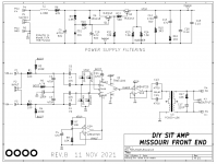
Begin by verifying that the top half of the Missouri schematic is working: measure the voltage between VTOP and GND. I find it easiest to do this if I insert a piece of hookup wire into the "PSU GND" euroblox terminal, and connect my scope GND / DVM blackprobe to that piece of wire.
VTOP is on the flywires (exposed metal, bent leads) of bleeder resistors R13 and R14, if you stuffed the PCB following the silkscreen guidance. Is VTOP somewhere in the neighborhood of 27-29 volts, as it should be?
Integrated circuit U2 pin 7 is supposed to be connected to VTOP so measure the voltage on that pin. Is it correct? U1 pin 8 is supposed to be connected to VTOP so measure the voltage on that pin. Is it correct?
Then verify that U2 pin 4 is at 0.00 volts (GND) as it should be. Verify that U1 pin 4 is at 0.00 volts.
Verify that "VHALF" is indeed half of the VTOP voltage as it should be. Measure VHALF at U1 pin 1 and also at U2 pin 1.
Now connect a signal generator (or phone with a signal generator app) to VIN++ and VIN--. Verify with a scope (alligator clip to PSU GND) that signal appears at U2 pin 3.
Verify that U2 is functioning correctly as a differential-to-single-ended converter. Verify with a scope (alligator clip to PSU GND) that signal appears at U2 pin 6, at the expected amplitude and not teeny tiny rinky dinky.
Verify that U1B is functioning correctly as a unity gain buffer. Does signal appear at U1 pin 7?
_
The first thing I'd do is carefully remove all ICs from their sockets and inspect the pins of each chip. Sometimes they get inserted wrong and the lead folds under, giving poor contact or no contact. Straighten the pins and triple check the part numbers and the pin-1 indicators, before reinserting them into their sockets. Swapping the chips, or inserting them backwards, is not what you want.
Begin by verifying that the top half of the Missouri schematic is working: measure the voltage between VTOP and GND. I find it easiest to do this if I insert a piece of hookup wire into the "PSU GND" euroblox terminal, and connect my scope GND / DVM blackprobe to that piece of wire.
VTOP is on the flywires (exposed metal, bent leads) of bleeder resistors R13 and R14, if you stuffed the PCB following the silkscreen guidance. Is VTOP somewhere in the neighborhood of 27-29 volts, as it should be?
Integrated circuit U2 pin 7 is supposed to be connected to VTOP so measure the voltage on that pin. Is it correct? U1 pin 8 is supposed to be connected to VTOP so measure the voltage on that pin. Is it correct?
Then verify that U2 pin 4 is at 0.00 volts (GND) as it should be. Verify that U1 pin 4 is at 0.00 volts.
Verify that "VHALF" is indeed half of the VTOP voltage as it should be. Measure VHALF at U1 pin 1 and also at U2 pin 1.
Now connect a signal generator (or phone with a signal generator app) to VIN++ and VIN--. Verify with a scope (alligator clip to PSU GND) that signal appears at U2 pin 3.
Verify that U2 is functioning correctly as a differential-to-single-ended converter. Verify with a scope (alligator clip to PSU GND) that signal appears at U2 pin 6, at the expected amplitude and not teeny tiny rinky dinky.
Verify that U1B is functioning correctly as a unity gain buffer. Does signal appear at U1 pin 7?
_
Attachments
Thanks Mark, that's stunningly helpful. This morning I saw that one of the ICs wasn't fully in and I hoped that would be an easy fix, no such luck! I'll work through the other steps and hopefully it'll be in business soon.
Cygnus, I have believe I have 1 spare PSFILT board left if that would work for you, drop me a message if you like and we can arrange.
Cygnus, I have believe I have 1 spare PSFILT board left if that would work for you, drop me a message if you like and we can arrange.
I'll run through how I've connected for good orders sake - I have no lab PSU so it's:Begin by verifying that the top half of the Missouri schematic is working: measure the voltage between VTOP and GND. I find it easiest to do this if I insert a piece of hookup wire into the "PSU GND" euroblox terminal, and connect my scope GND / DVM blackprobe to that piece of wire.
VTOP is on the flywires (exposed metal, bent leads) of bleeder resistors R13 and R14, if you stuffed the PCB following the silkscreen guidance. Is VTOP somewhere in the neighborhood of 27-29 volts, as it should be?
Meanwell supply > PSFILT board > PSFILT CH2_V+ > FE PSU_V+
PSFILT CH2_GND > FE PSU GND & hookup wire from here
Just to confirm, I then measure 36 vdc between FE PSU_V+ & FE PSU GND
Between FE PSU GND & VTOP (either of the tops of R13 and R14) I get 0 VDC
It's fair to assume that the problem is in the power supply filter half then as the power isn't going through the circuit?
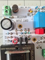
You might have stuffed R13 and R14 backwards (opposite to silkscreen guidance) and since you didn't attach a photo, nobody knows.
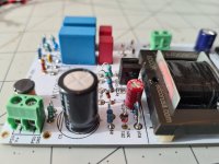
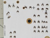
Post a clear, close up photo of the top left 1/4th of your failing PCB, showing R6, R9, R10, R11, R12, R13, R14 and the silkscreen words "MISSOURI INPUT CARD".
Then, with voltmeter blackprobe connected to PSU GND, measure and record seven voltage readings. Measure with voltmeter redprobe connected to the flywires of those seven resistors: R6 R9 R10 R11 R12 R13 R14 . These measurements will help you narrow down the investigation and figure out where the original fault might be.
Just to name one example, using one of those voltage measurements: If the voltage on the flywire of R6 is not +36V or thereabouts, that means there's something wrong with either P5 or L1 or R6. {do you see why?} The problem might be incorrect stuffing, bad soldering, failed component, etc. You need the voltage measurement(s) to decide where attention should be focused.
Example 2: If the flywire of R10 is not +30V or thereabouts, that means something's wrong with Zener diode ZD1. {do you see why?} Bad soldering, diode failure, installed backwards, etc. You need the voltage measurement(s) to decide where attention should be focused.
I'm with you and appreciate you showing me how I narrow it down, segment by segment, I would not have known / learnt that otherwise. Photos also attached, I can see how that would help...You might have stuffed R13 and R14 backwards (opposite to silkscreen guidance) and since you didn't attach a photo, nobody knows.
Post a clear, close up photo of the top left 1/4th of your failing PCB, showing R6, R9, R10, R11, R12, R13, R14 and the silkscreen words "MISSOURI INPUT CARD".
Then, with voltmeter blackprobe connected to PSU GND, measure and record seven voltage readings. Measure with voltmeter redprobe connected to the flywires of those seven resistors: R6 R9 R10 R11 R12 R13 R14 . These measurements will help you narrow down the investigation and figure out where the original fault might be.
Just to name one example, using one of those voltage measurements: If the voltage on the flywire of R6 is not +36V or thereabouts, that means there's something wrong with either P5 or L1 or R6. {do you see why?} The problem might be incorrect stuffing, bad soldering, failed component, etc. You need the voltage measurement(s) to decide where attention should be focused.
Example 2: If the flywire of R10 is not +30V or thereabouts, that means something's wrong with Zener diode ZD1. {do you see why?} Bad soldering, diode failure, installed backwards, etc. You need the voltage measurement(s) to decide where attention should be focused.
For measurements I get:
R6 - 35.7
R9 - 34.5
R10 - 29.9
R11 - 0
R12 - 29.1
R13 - 0
R14 - 0
So the problem looks like the capacitor at C10 then as it stops the circuit completing at R11 but at R12 it can go around it. When I measure it, it the multimeter does go up, down and everywhere not staying at 47k. Does that seem correct?
Attachments
- Home
- Amplifiers
- Pass Labs
- Ship Of Theseus: compatible, interchangeable amplifier modules