Easy : 10 speakers at 8 ohms, so 20 speakers total in stereo ! I do not consider this a simple solution vs. a fixed bias operation of a single 6080... Plus it's not versatile : these 72R speakers or nothing.
I built in 1983 my first OTL with one 6080, using decoupled cathode bias. It proved to be a poor idea, and I shifted to fixed bias quickly : distortion, bandwidth and power output were significantly improved. In fact, the cathode bias operation - but with un-decoupled cathode resistors - worked as fine as the fixed bias operation, but the drawback was that the power output was correct for... An headphone amp.
With a decoupled cathode bias operation - even with 3300µF - a 6AS7 or a 6080 in OTL circuit won't be able to offer the square waves as I displayed in my post #56, unless you apply a high level of NFB :
https://www.diyaudio.com/community/threads/simple-otl-for-beginners.407554/post-7566933
Nonetheless, yes : 10 speakers in serie par channel, that's perfectly doable, but what is not in the amp is compensated by the number of speakers : not more simple and rigid solution, IMHO - not for me, at least !
But it's me, OK ? 😉
T
Indeed, the speakers will be a lot of work. Still, I think it is a matter of what one likes to do. What I like most is to work with different amplifier topologies. To actually use these, I need a source, and speakers. So I looked around, learned, put myself a source together to have nice music. But I am not looking to do it again, and the next source was just a PC with a USB DAC. I am slowly starting to work on my own loudspeakers, but at a much slower pace than amplifiers. I see many around here that like woodworking and therefore made multiple pair of speakers, but maybe only one amp, or use commercial stuff.
It happens that two of my speakers are line arrays, they are so nice!! And they bring the advantage of being more friendly OTL loads, good excuse for me 🙂
The 72R speakers would consist of 9 speakers of 8R, they can be reconfigured as an 8 ohm load for more conventional amps.
Last edited:
The author of the thread asked for a simple OTL for beginners. Do you remember when you were a beginner? I remember, some 20 years ago. Making an amplifier with a single ECL82 was such a hard thing, what are all these components?, what should I take?, why is it making weird noises? Why did the cap explode? The author already mentioned that he is a beginner, so I am trying to keep it simple for him. Surely will not be high end and the best, but, as I read from Tubecad : the perfect is the enemy of the build.I'm not sure that 2 quite big caps 3300µF/63V plus a duet of heating resistor is much better about simplicity - and moreover - reliability than a fixed bias operation OTL, in this particular case.
I built those 20W OTL with 4x6080 / 20WRMS fixed bias (below) in 1996, I sold them in the mid-2000 to a friend who still owns them without issue since then, if we except a set of new tubes :
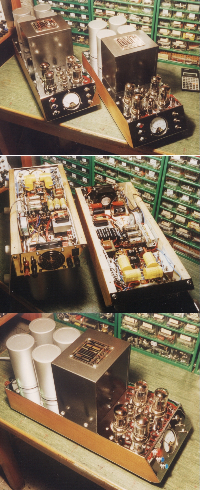
I sold them because... They were heavy and big ! 🙄 But that's nonetheless true, compared to the size of my U-OTL of today !
T
So when I think simple, I think about the minimum possible number of components and adjustments, and there the auto bias 6AS7 clearly wins over fixed bias, still being able to deliver the circa 5W into 72R.
Still I am currently making a more powerful OTL with fixed bias: yesterday I put the 3 extra 7VAC windings on the toroidal, they feed voltage quadrupliers for generating about 32V for the fixed bias. This toroidal I took out of some discarded equipment. It had an 18V winding to which I added some more windings to get 22V for the 22JF6, then I added a 6.3V for the E180F drivers, and yesterday the three above-mentioned windings.
Last edited:
Thanks T,
You posted a lot of pictures of your OTL, but I did not see a schematic. Can you share it?
Many thanks,
Erik
You posted a lot of pictures of your OTL, but I did not see a schematic. Can you share it?
Many thanks,
Erik
Thanks T,
You posted a lot of pictures of your OTL, but I did not see a schematic. Can you share it?
Many thanks,
Erik
Yes @ErikdeBest : I like to post images, it speaks better, and follows as far as possible the rule "No picture ? Never existed !" 😉
Without wanting to show up, OK ? I must confess that I am sometimes reluctant to share my schematics, because I found many of them on several websites, webpages and forums, posted by people who claim to be the creator, or commented by pseudo-experts - if you see what I mean... Like "poor design, too small, it will burn, too simple, it won't work, you should have used a 12AYFG8BZ in ultra-cascode-bootstrap-fet-machin !" 😱🤣
But I follow the rule here : "pictures, it exists, and it works"...
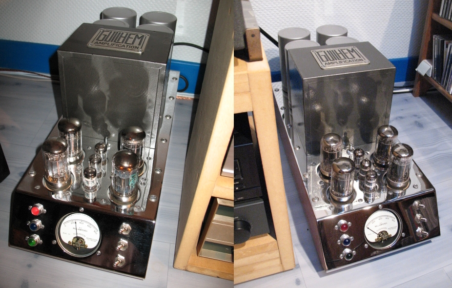
The protoype under tests in 2020-2021 :
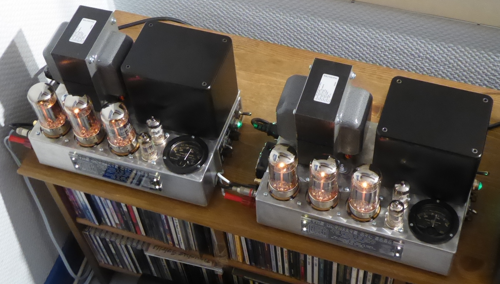
The finished version in late 2021 :
I usually use them to drive a pair of Triangle T17FL2 fullrange DIY speakers or a pair of Klipsch Heresy I (with corrected crossover).
Here's the matching schematic of one mono block - you recognize Mr Futterman's 1956 original OTL patent principle :
And the inside layout :
SPECS :
- nominal power output 10WRMS 16R.
- input sensivity = 0.675V @10W.
- THD = to be measured soon... One of these days... When I'll have my measurement gear set up again !
- bandwidth = 1Hz-200KHz @-3dB 10WRMS 16R.
- output impedance = 20 Ohms.
- no global feedback loop.
T
Last edited:

IMHO one solution and substitute for full tube OTL can be the Hybrid AB-class OTL amp , where input voltage gain stage and driver stage remains tubes, but output power devices are modern RF Lateral Mosfets , for example NXP- MRF101 , intented for linear amplification with relative low internal capacitances , it is one very ruged and easy available 182W device .
Attachments

Is another hybrid solution to create a low impedance output stage, and then the requirements for the OPT make it much easier to use a smaller and cheaper one. The original poster only wanted to avoid the iron and copper of a big OPT.
Just put some constant Beta bipolar transistors under the output tube's cathodes to form a Darlington output for each. Can still be an OTL like design. Then you still have some "output tubes" to display on the chassis. Some little 48V switching power supplies to power the output stage transistor collectors.
Last edited:
I have seen such solution but I don`t like it because over the time such hybrid OPS will shift DC parameters in function of asociated tubes aging , mine idea is to use small signal pentode/triode tube such is ECF80 or simmilar tubes to directly AC drive the gates of SEPP-OPS , since driving power @20Khz is not more than 100mW for those lateral RF- N-type power mos-fets , and what ever happened to parameters of ECF80 tube OPS-DC parameters will stay stable , positive side of those RF-Mosfets is that they have negative tempco, so no special temperature compensation unit is neded ,
of course my schematic form post #87 is only conceptual , since in reality positive bias network for OPS is a little different , ...
of course my schematic form post #87 is only conceptual , since in reality positive bias network for OPS is a little different , ...
Last edited:
Then you still have some "output tubes" to display on the chassis.
This gives me an idea : a small OTL with a single 6080 and two 12AU7, just heated, not connected, and the amp by itself is a tiny Class D kit hidden in the chassis... I'm sure some would recognize the qualities of a tube amp ! 🤔😆😉
T
Properly designed and properly implemented Double Blindfold listening tests (easier said than done) . . .
Can be your friend, or can be your enemy . . .
Depending on which outcome you want to prove.
Can be your friend, or can be your enemy . . .
Depending on which outcome you want to prove.
The linear MRF Lateral Mosfet outputs will probably sound -more- linear than the real OTL.
The bipolar NPN Darlingtons will just multiply up (Beta ) the "output" tube currents, so should still sound just like a tube OTL. Re-biasing for aging tubes is just normal procedure for any tube Amp. The "output" tubes here will just be small signal tubes in the Darlington case. Should last a long time. NPNs doing the grunt work. Maybe 6197 tubes, got tons of them, $ 0.35 each. (nice curves below)
" tiny Class D kit hidden in the chassis..." Aw c'mon now, that's just cheating TOO much.
I'm ordering an 80 Watt 1200 ct P-P OT to make a trial P-P Amp with two 6528 regulator tubes. With a switch to flip in or out the two resistors for the OTL cheat patent. 80 Watts conventional OT P-P or 80 Watts TOT. ( Transparent OT !! ) 6528 pics at bottom.
Last edited:
Thanks for sharing, one can learn quite something from it!Yes @ErikdeBest : I like to post images, it speaks better, and follows as far as possible the rule "No picture ? Never existed !" 😉
Without wanting to show up, OK ? I must confess that I am sometimes reluctant to share my schematics, because I found many of them on several websites, webpages and forums, posted by people who claim to be the creator, or commented by pseudo-experts - if you see what I mean... Like "poor design, too small, it will burn, too simple, it won't work, you should have used a 12AYFG8BZ in ultra-cascode-bootstrap-fet-machin !" 😱🤣
But I follow the rule here : "pictures, it exists, and it works"...
The protoype under tests in 2020-2021 :
View attachment 1262137
The finished version in late 2021 :
View attachment 1262138
I usually use them to drive a pair of Triangle T17FL2 fullrange DIY speakers or a pair of Klipsch Heresy I (with corrected crossover).
Here's the matching schematic of one mono block - you recognize Mr Futterman's 1956 original OTL patent principle :
View attachment 1262121
And the inside layout :
View attachment 1262140
View attachment 1262139
SPECS :
All this in a 275x175x66mm aluminium chassis : why go big when small is possible ? 😉
- nominal power output 10WRMS 16R.
- input sensivity = 0.675V @10W.
- THD = to be measured soon... One of these days... When I'll have my measurement gear set up again !
- bandwidth = 1Hz-200KHz @-3dB 10WRMS 16R.
- output impedance = 20 Ohms.
- no global feedback loop.
T
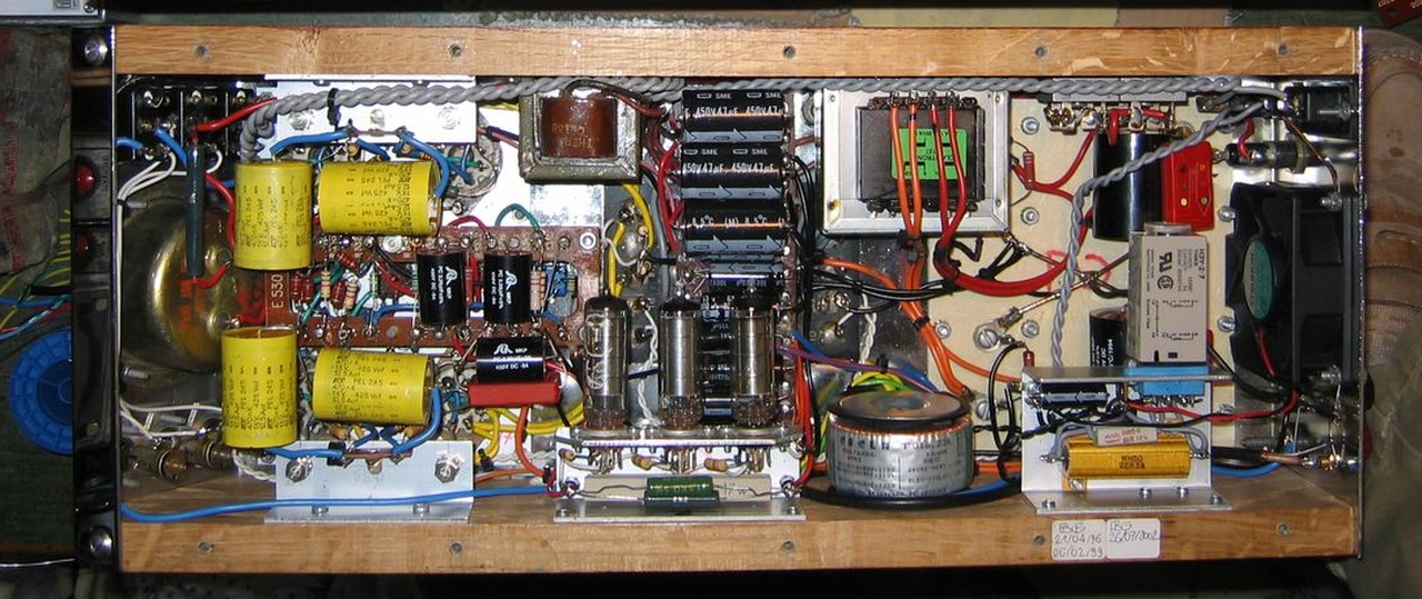
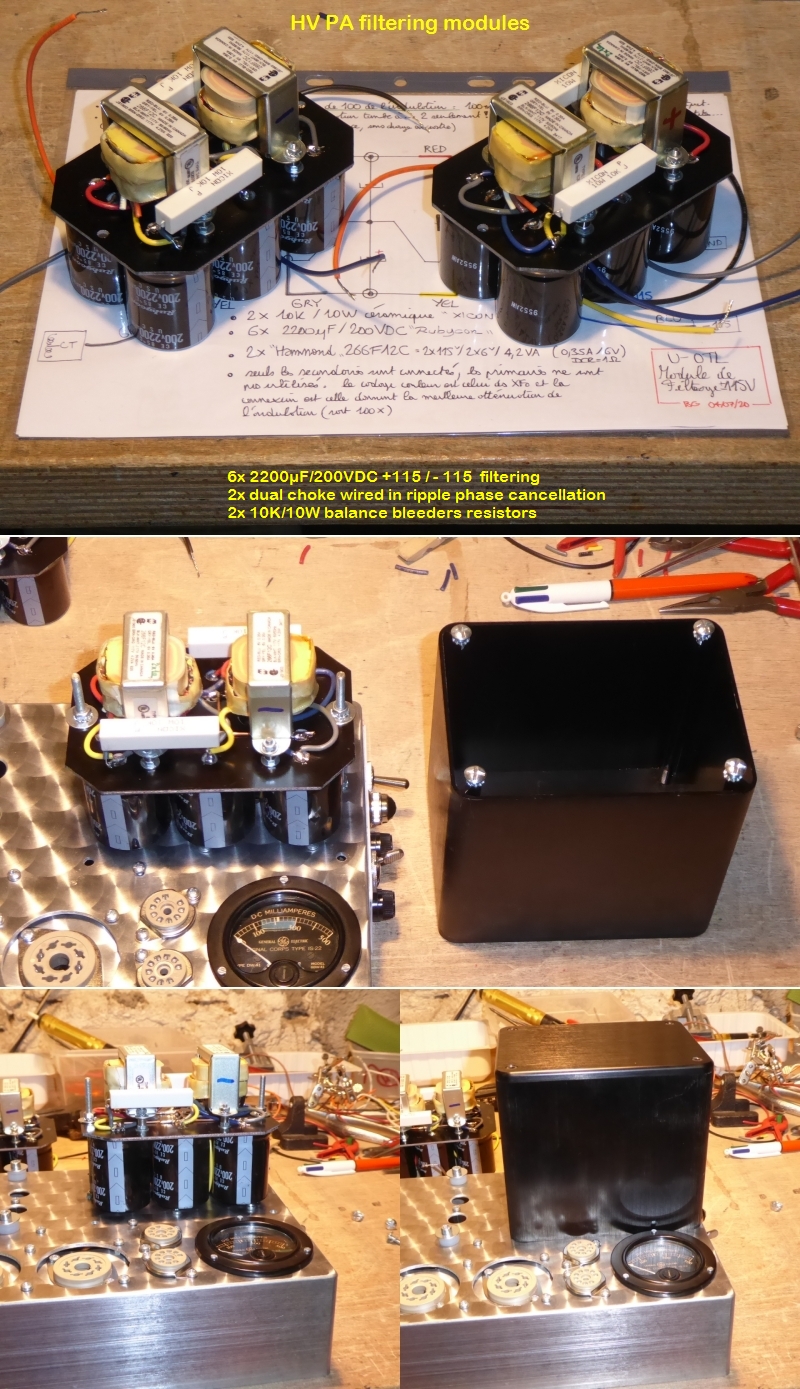
Are the fuses normal 20x5mm ones (with normal I mean rated for 250V AC?) Interesting use of the Hammonds in the filtering, I imagine you use the 6V windings? Are the 115V in parallel to them? How are the phases connected? Reminds me of these by Lundahl https://www.lundahltransformers.com/wp-content/uploads/datasheets/2733.pdf
My OTL with the 22JF6 is running now as well, still some "little issues" with it though. Stereo chassis with 35W power/channel, not heavy at all (but I use toroidal transformers, for the power stage a 500VA one I got from a surplus store).
I will come back with more questions 🙂
Thanks for sharing, one can learn quite something from it!
Are the fuses normal 20x5mm ones (with normal I mean rated for 250V AC?) Interesting use of the Hammonds in the filtering, I imagine you use the 6V windings? Are the 115V in parallel to them? How are the phases connected? Reminds me of these by Lundahl https://www.lundahltransformers.com/wp-content/uploads/datasheets/2733.pdf
My OTL with the 22JF6 is running now as well, still some "little issues" with it though. Stereo chassis with 35W power/channel, not heavy at all (but I use toroidal transformers, for the power stage a 500VA one I got from a surplus store).
I will come back with more questions 🙂
Yes. The fuses are standard 20x5mm 250V T1A.
Yes. I use the 6V windings, the 115V are not used (no advantages noted in hum cancellation). About the phase : sorry I don't remember, I simply searched the relative sense of the windings which offered the expected cancellation.
So what looks like your 22JF6 OTL, then ? 🤔
T
Thanks for the reply! So, the idea of the chokes is that they are connected as in this schematic by Jac-Music? Note this is not the CMC connection, normally used in audio. https://jandkaudiodesign.blogspot.com/2015/04/2-coil-choke.html
My experiments with OTL are described here at diyaudio.
The one with pictures is based on the 17KV6 auto bias. Thread with pictures is here https://www.diyaudio.com/community/threads/beam-power-pentode-otl.391888/
The 22JF6, currently under the workbench, was suffering from motorboating until I increased the load at the output. It did not catch much attention, rather a monologue. https://www.diyaudio.com/community/threads/beam-power-otl-shifting-bias-levels.403061/ In the meantime, I raised the voltage for the driver to about 450V DC. I can post some pictures: my camera (phone) is not great, and I like to discuss schematics more than pictures.
My OTL experiments started here https://www.diyaudio.com/community/threads/nfb-in-circlotron-more-nfb-higher-thd-why.389662/ this one based on circlotron. Give up on it because I would have to buy more power transformers for decent PS (would like 4 transformers for the output stage of a stereo amp) while I had a 500VA available for the Futterman.
Attachments

Thanks for the reply! So, the idea of the chokes is that they are connected as in this schematic by Jac-Music? Note this is not the CMC connection, normally used in audio. https://jandkaudiodesign.blogspot.com/2015/04/2-coil-choke.html
Oh, I experimented this cancelling-hum-transformer trick in the early-80s, with my first OTL amps... You can see it in this later 1996 20W/16R version below :
And in the present U-OTL :
My experiments with OTL are described here at diyaudio.
Have you been further ? I mean : is there any finished versions of those prototypes ?
T
The one with the 17KV6 played the highs in my main system for a couple of months, it was replaced with a SE 6S4S (sort of a 2A3), so is playing good and well. I just got the 22JF6 stable, so will be tested for the bass in the main system (maybe together with the 17KV6 OTL). The circlotron was only tested mono with my bench PS, as I said before, I do not have the required power transformers for it.
Currently, my home setup does not allow exposed amplifiers, so I use (hide) these in a well ventilated cabinet. That they don't look nice does not mean they do not play nice 🙂
Thanks for the detailed pictures of the filters. Looks like they are not in CMC connection (so more like the schematic from Jac Music). I just use plain 3W 3R resistors and big caps, also no hum on the speakers.
Old thread, but this schematic remembered one thing I built in 2010, almost equal to it.IMHO one solution and substitute for full tube OTL can be the Hybrid AB-class OTL amp , where input voltage gain stage and driver stage remains tubes, but output power devices are modern RF Lateral Mosfets , for example NXP- MRF101 , intented for linear amplification with relative low internal capacitances , it is one very ruged and easy available 182W device .
I liked very much this all-N solution when I first see it at that time, but...
The problem with it proved to be when the output gets in saturation. With every cap coupled high feedback amp, the coupling charges when the output ceases to respond to signal. This plays havoc for some time, making some big thump in the speakers, since the MOSFET goes to full saturation ("pumping"). Tube OTL with feedback also have this effect, but is more gentle, since tubes have less transconductance and not "switches" with low rds(on).
I bet your RF Lateral MOSFET can have better behaviour due to more relaxed saturation of it (I used vertical MOSFETs).
And gate zener protection is paramount here, also due to this.
One solution for it is never using it with low eff. speakers, for not saturating the output.
OTL not having global feedback is inmune to this by design.
That simple hybrid amp based on J.Futterman original OTL concept have one advantage that from main transformer one single secondary you can have both B+lines , one high power B+ line for solid state OPS ,and also one low power B+(x2) line for tube part using simple voltage doubler .
Attachments

- Home
- Amplifiers
- Tubes / Valves
- Simple OTL for beginners?