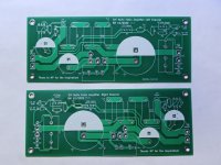
Hi Ben Mah,If you would like a copy of the Gerber files, place a request here on this thread.
Would like to have a copy of the Gerber files. Thanks.
SMathews
Hi everyone,
Thanks for all of the great comments that I have been receiving, both in private messages and here on the forum.
For those people who have not received the Gerber files, they will be sent out later today. My level of paid membership allows me to send 10 messages per 24 hours to individual members. I had sent 10 out last evening so I need to wait a bit before I can sent more.
Ben
I predict a thread titled .... "Show off your HOT Mufo ! " .Accompanied by photos of IR guns and questions concerning 60deg C operating temps.
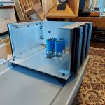
Out of curiosity and because it's Saturday. I decided to blast a heat gun in the center of the future device mount location. I went 10 min. or so. Nothing concerning occurred but I am rethinking the location of the rectifiers. Silicone foam pads for isolating transformers and capacitors are already on hand.
Onward!
Attachments
I just checked. To clarify, I can start 10 new conversations per 24 hours. So I will be able to send more Gerber files in about six hours.
Citation19, That looks like a lot of aluminum, but do you have enough heat sink fins? The aluminum will absorb the heat, and with the amount that you have, it will take a while to heat up. But surface area is needed to dissipate heat. If the surface area is low, then the temperature will stabilize at a high value whereas if the surface area is high, the temperature will stabilize at a lower value.
Perhaps your whole chassis will heat up and have enough surface area to dissipate the heat while maintaining a reasonable temperature.")
Citation19, That looks like a lot of aluminum, but do you have enough heat sink fins? The aluminum will absorb the heat, and with the amount that you have, it will take a while to heat up. But surface area is needed to dissipate heat. If the surface area is low, then the temperature will stabilize at a high value whereas if the surface area is high, the temperature will stabilize at a lower value.
Perhaps your whole chassis will heat up and have enough surface area to dissipate the heat while maintaining a reasonable temperature.
Yeah...I hear you. The amount of Physics being overlooked and replaced with brute force and hope is at a fairly high level here. Maybe it will work?
I plan to keep the current low at first, go for it, wait a short eternity for this thermal mass to stabilize, and watch closely. Luckily I can swap the sinks out easily....Past that there is a gut feeling that cutting holes in the channel and mounting the devices directly to the heat sink will be preferred. I'll make it happen, there are options.....I also have fans !
I plan to keep the current low at first, go for it, wait a short eternity for this thermal mass to stabilize, and watch closely. Luckily I can swap the sinks out easily....Past that there is a gut feeling that cutting holes in the channel and mounting the devices directly to the heat sink will be preferred. I'll make it happen, there are options.....I also have fans !
They do look like bars but are in fact more heat sinks nested within heat sinks. That's 4 thermal junctions for the Sit to transfer through to get to those nested sinks. Sit/Ceramic wafer/.5" aluminum/heatsink/nested heatsink.Less for the current device. Not pretty from a physics design point of view.
This is a lesson.....just pay the $450 for the 5Ux400 Dissipante and be done with it. However, I am having fun tinkering
This is a lesson.....just pay the $450 for the 5Ux400 Dissipante and be done with it. However, I am having fun tinkering
Attachments
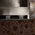
Ah ..., my mistake. However, the fins on the nested heatsinks are too close together for air flow without a fan. Heatsinks for passive air flow have fins that are thick to allow heat flow and widely spaced out to avoid boundary layer issues. I think replacing those nested heatsinks with a length of thick angle would actually lower the thermal resistance compared to those nested heatsinks.
Yes, sometimes the proper solution is cheaper in the long run. I have experience with that.
Yes, sometimes the proper solution is cheaper in the long run. I have experience with that.
That's a lot of thermal interfaces/junctions to deal with.
The fins on the nested heat sinks are very close together so natural convection is not very effective. My understanding is that 6mm or so of space between fins is necessary for effective natural convection, and is optimum at about 12mm. Less than that and they start to behave more like a solid bar for air flow.
The fins on the nested heat sinks are very close together so natural convection is not very effective. My understanding is that 6mm or so of space between fins is necessary for effective natural convection, and is optimum at about 12mm. Less than that and they start to behave more like a solid bar for air flow.
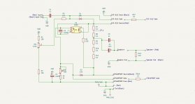
PARTS LIST
HF-51S MuFo Fokin Parts List (One Channel): Values, Max. Footprint and lead spacing, and what I used:
C1, C5 4uF coupling cap 80V min (at output) 32mmx15mm, 27.5mm, https://www.mouser.ca/ProductDetail/75-MKP1848C54090JK2 (4uF)
C2 1000uF 80V, 18mm dia, 7.5mm, https://www.mouser.ca/ProductDetail/661-EKYB800E102MLP1S (1000uF)
C3 1000uF 63V Audio, 18mm dia, 7.5mm, https://www.mouser.ca/ProductDetail/647-UKW1J102MHD (1000uF)
C4 10mF 80V Audio, 35mm dia, 10mm, https://www.mouser.ca/ProductDetail/80-ALC10S1104DL (10mF)
U1 4N35, https://www.mouser.ca/ProductDetail/78-4N35 (4N35)
U1 Socket 6 pin socket, https://www.mouser.ca/ProductDetail/575-113306 (Socket)
)
RV1 100kOhm 1/2W Trimmer, https://www.mouser.ca/ProductDetail/81-PV36W104C01B00 (100k Trimmer)
R1,R2 16k 1/4W, 7.5mm, https://www.mouser.ca/ProductDetail/603-MFR-25FTE52-16K (16k)
R3 10k 1/2W Trimmer, https://www.mouser.ca/ProductDetail/81-PV36W103C01B00 (10k Trimmer)
R4 3k 1/4W, 7.5mm, https://www.mouser.ca/ProductDetail/603-MFR-25FTE52-3K (3k)
R5 10k 1/4W, 7.5mm, https://www.mouser.ca/ProductDetail/603-MFR-25FRF5210K (10k)
R6 100R 1/4W, 7.5mm, https://www.mouser.ca/ProductDetail/603-MFR-25FTF52-100R (100R)
R7-R11 0.1R 3W, 20mm, https://www.mouser.ca/ProductDetail/279-ROX3SJR10 (0.1R)
D1,D2 18V 1/2W, 7.5mm https://www.mouser.ca/ProductDetail/78-BZX55B18 (18V)
Not included in above list:
R12, R14 22R 0.25W, mount in series at Mosfet and SIT gate
R13 220R 3W, mount across speaker output+ and Gnd
THF-51S
IXTN40P50P Alternates:IXTN90P20P, IXTN170P10P
Notes:
1. R1, R2, R4, R5, R6, D1, D2: 7.5mm pad spacing on PCB, mount longer resistors at an angle or vertically. The resistors and zener diodes that I chose were short enough to mount flat against the board.
2. Resistors and zener at Test Points were elevated above the board for clip lead attachment.
3. When it comes to low cost items (resistors) and sensitive items that are low cost (i.e. 4N35, zeners), buy more than the exact amount that you need. That may save you time and money if you need a replacement during your build.
Attachments
Last edited:
- Home
- Amplifiers
- Pass Labs
- Single Ended Tokin SIT THF-51S Common Drain Mu Follower Amplifier, 45W?