On the subject of parts, if you don't have an 8 Ohm test load, I suggest you purchase two 4 Ohm 50W resistors and mount them on a heat sink or metal plate. It will be handy when it comes time to power up and test the amplifier. It can be done without it, but having a test load allows you to test the current source separately before connecting the SIT. It is better for peace of mind, and allows for less stress. ")
It can then be used for testing the completed amplifier if you have a FFT rig.
Example of 4R 50W resistor
It can then be used for testing the completed amplifier if you have a FFT rig.
Example of 4R 50W resistor
Thanks for that parts list. The links to Mouser go above and beyond so much appreciated.PARTS LIST
HF-51S MuFo Fokin Parts List (One Channel): Values, Max. Footprint and lead spacing, and what I used:
I think you said that you didn't actually build the power supply that you designed? So no parts list for that?
Ciatation19, I wouldn't say definitely no. However at start-up or during initial set-up, the voltage may be at power supply voltage until current flows. Once running, the voltage will be much lower, at around 33V. During setup, when the SIT is not connected and current is not flowing, the power supply voltage my be at the capacitor for the period that it is powered up. My power supply outputs up to about 65V or so under no load so I decided to err on the safe side. On the other side of the capacitor is my speaker.
If your power supply outputs less than 63V under no load, it may be doable. But capacitors can fail. For me, I value my speakers so I played it safe.
This is do-it-yourself so you are the master of your own domain.
I leave the decision to you.
If your power supply outputs less than 63V under no load, it may be doable. But capacitors can fail. For me, I value my speakers so I played it safe.
This is do-it-yourself so you are the master of your own domain.
I leave the decision to you.
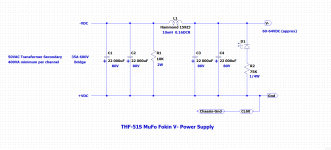
Paul, My power supply was done nearly two years ago so no, it was not built on my just designed PS board. However what I built nearly two years ago fits on the board.
Here is the schematic. I have not included the AC circuit but that is no different from the typical power supply seen on this forum.
If you are going to use my PS board, you need to choose capacitors with 5 pins.
An example: 22mF 80V
Here is the schematic. I have not included the AC circuit but that is no different from the typical power supply seen on this forum.
If you are going to use my PS board, you need to choose capacitors with 5 pins.
An example: 22mF 80V
Attachments
It should work with no parts change. The alternates were originally suggested by Zen Mod in his Lazy Singing Bush thread (P-Channel Mosfets)
Thanks. D1 is just an LED to show that the power is on? I consistently seem to fry those either installing them backwards or having them underrated for the voltage they see.Paul, My power supply was done nearly two years ago so no, it was not built on my just designed PS board. However what I built nearly two years ago fits on the board.
Here is the schematic. I have not included the AC circuit but that is no different from the typical power supply seen on this forum.
If you are going to use my PS board, you need to choose capacitors with 5 pins.
An example: 22mF 80V
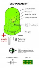
Yes, the LED will show that the power is on. More importantly it also indicates that the capacitors are charged, so if you are about to work on your power supply, you can visually check before you dive in.
The LED has an appropriately sized voltage dropping resistor in series with it so overvoltage should not be a problem. The longer LED lead, the anode, is always connected to the more positive side of the circuit. In this case that would be the Ground side as the other side is V-. With my PS board, the long lead goes into the round pad (the pad closest to the resistor).
The LED has an appropriately sized voltage dropping resistor in series with it so overvoltage should not be a problem. The longer LED lead, the anode, is always connected to the more positive side of the circuit. In this case that would be the Ground side as the other side is V-. With my PS board, the long lead goes into the round pad (the pad closest to the resistor).
Attachments
Last edited:
would you please share the KiCAD file to us?PARTS LIST
HF-51S MuFo Fokin Parts List (One Channel): Values, Max. Footprint and lead spacing, and what I used:
C1, C5 4uF coupling cap 80V min (at output) 32mmx15mm, 27.5mm, https://www.mouser.ca/ProductDetail/75-MKP1848C54090JK2 (4uF)
C2 1000uF 80V, 18mm dia, 7.5mm, https://www.mouser.ca/ProductDetail/661-EKYB800E102MLP1S (1000uF)
C3 1000uF 63V Audio, 18mm dia, 7.5mm, https://www.mouser.ca/ProductDetail/647-UKW1J102MHD (1000uF)
C4 10mF 80V Audio, 35mm dia, 10mm, https://www.mouser.ca/ProductDetail/80-ALC10S1104DL (10mF)
U1 4N35, https://www.mouser.ca/ProductDetail/78-4N35 (4N35)
U1 Socket 6 pin socket, https://www.mouser.ca/ProductDetail/575-113306 (Socket)
)
RV1 100kOhm 1/2W Trimmer, https://www.mouser.ca/ProductDetail/81-PV36W104C01B00 (100k Trimmer)
R1,R2 16k 1/4W, 7.5mm, https://www.mouser.ca/ProductDetail/603-MFR-25FTE52-16K (16k)
R3 10k 1/2W Trimmer, https://www.mouser.ca/ProductDetail/81-PV36W103C01B00 (10k Trimmer)
R4 3k 1/4W, 7.5mm, https://www.mouser.ca/ProductDetail/603-MFR-25FTE52-3K (3k)
R5 10k 1/4W, 7.5mm, https://www.mouser.ca/ProductDetail/603-MFR-25FRF5210K (10k)
R6 100R 1/4W, 7.5mm, https://www.mouser.ca/ProductDetail/603-MFR-25FTF52-100R (100R)
R7-R11 0.1R 3W, 20mm, https://www.mouser.ca/ProductDetail/279-ROX3SJR10 (0.1R)
D1,D2 18V 1/2W, 7.5mm https://www.mouser.ca/ProductDetail/78-BZX55B18 (18V)
Not included in above list:
R12, R14 22R 0.25W, mount in series at Mosfet and SIT gate
R13 220R 3W, mount across speaker output+ and Gnd
THF-51S
IXTN40P50P Alternates:IXTN90P20P, IXTN170P10P
Notes:
1. R1, R2, R4, R5, R6, D1, D2: 7.5mm pad spacing on PCB, mount longer resistors at an angle or vertically. The resistors and zener diodes that I chose were short enough to mount flat against the board.
2. Resistors and zener at Test Points were elevated above the board for clip lead attachment.
3. When it comes to low cost items (resistors) and sensitive items that are low cost (i.e. 4N35, zeners), buy more than the exact amount that you need. That may save you time and money if you need a replacement during your build.
I am considering using my chassis built around two SK 139 200 mm heat sinks, see here.
These are 0.24 K/W each. Using 60V and 2.5 A bias gives me 150W and 36 K temperature rise, which corresponds to around 60 degrees C on the heat sinks. I feel this is marginal, but comments are welcomed.

These are 0.24 K/W each. Using 60V and 2.5 A bias gives me 150W and 36 K temperature rise, which corresponds to around 60 degrees C on the heat sinks. I feel this is marginal, but comments are welcomed.
- Home
- Amplifiers
- Pass Labs
- Single Ended Tokin SIT THF-51S Common Drain Mu Follower Amplifier, 45W?