All,
Just a follow up...
I did a test with three paralel IRFP9240, using the current sharing that ZM helped me do. At 2.5A bias current and 33V Vds on the SIT I let it run for a couple of hours and everything was stable. I didn't put a signal through it. So if anyone want to take this further, this was my results to date.
I felt it was a bit ugly as the extra R's on the source were just point to point wired and I think a nice layout will always give me a more reliable unit.
I was still having a hard time getting a good IXYS part from the recommended list in my current region, so I started doing a DS search for other options with better availibilty. IXTH16P60P came up as a potential part, so I ordered a couple to try. This is in the TO-247 package and the RthJC is about 2 times that of the hockey puck packages in the orginal design. But after a calculation I think it should work as Ben's orginal plan was 3.0A bias and I only plan on running at 2.5A bias.
I built it yesterday and let it run for a couple of hours and with everything the same as Ben's orginal schematic, it biased up perfectly. I have pretty big heatsinks, and both heatsinks felt 50-55C based on Nelson's touch temperture scale. They were hot but you could touch them. Bias current was very stable and the Vds across the SIT slowly moved down and with some adjustments was floating around 32.9-33.1C but stable in that range.
I would say this MOSFET is a viable option at 2.5A bias current.
Next I need to put a signal through it...
G
Hi
I was recently looking for a backup pair of THF-51S since they will eventually be nowhere to be found.
I contacted Tokin directly and their distributor contacted me.
To make a long story short, I bought a pair which are genuine but not a matched pair. Comes with a 1 year warranty from the vendor.
They have a few left if anyone is interested, price is $35 per unit.
I don’t know the seller and not affiliated with them, just passing on some good news and btw I have received excellent service from them.
I haven’t tried the device yet but with the 1 year warranty I ain’t worried.
My goal was to do a GB but as of yesterday they only have 6 left.
PM me if interested.
Eric
Well done, @e_fortier !
I hope those elevator transistors work out well!
I hope those elevator transistors work out well!
I wanted to give a big thanks to Ben for the design and of course a huge thanks to Nelson for the inspiration. I have completed, tested and listened to a pair of these over the weekend, and enjoy the results.
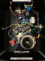
First a picture of the nearly finished amp. I have a few things to finish, but these are just minor issues, wiring the power button, zip tying and organizing the cables a bit better, and fitting a thermal protection switch that I have typically added to my class A builds.
I realize by posting this picture I open myself up to ZM poking fun of me for using screw terminal blocks on the PS filter board, but they have always worked well for me and if one of them opens up I will just loose power, so I'm ready to take the abuse")
My build, most notibly is different because I'm not using a hockey puck MOSFET, and instead using the IXTH16P60 that I mentioned a few posts above. Seems to work well at 2.5A bias current, hopefully it will last a long time in this position. I'm using an inexpensive softstart circuit, that will be controled by the switch. Transformer is 48V 400VA. The filter is being fed by schottky diode rectifier. For the PS filter I did my own layout for a CRCLC which outputs just over 60V when fully loaded by this circuit. For the sharp eyes you may notice my silkscreen mistake on the output, I have mislabled the V- incorrectly as V+. Potentially a very stupid and damaging mistake, but Ben recommends powering up the circuit in stages first with the PSU, and I measured the output and easily found the mistake. From the PSU I have a larger gauge wire running directly to the D on the MOSFET suppling -60V, and only a small wire running to the board for the small current needs of the rest of the circuit. On the SIT I have the D connexted ditectly to ground on the PSU and the SIT body itself connected to the chassis. Typically I have followed Nelson's design and isolated the chassis ground from the audio ground using a thermistor, but so far I have not done this on this amp.
Ben's build tips are great and for the first channel I built and tested on the test bench before moving into a case, when I moved it into a case I did little testing as I had it mostly setup well on the bench. For the 2nd channel I took a guess at some of the potentiometer settings and came darn close to my target, with the current at 2.4A and the SIT Vds at 32.8V, but I did find that I had problems testing it on the DBT with the softstart circuit in place, so maybe a hint is if doing the power up tests step by step, you should bypass the softstart if you are using one.
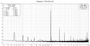
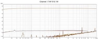
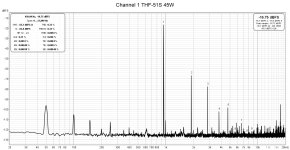
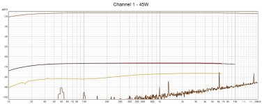
Testing I used REW, and am not an expert in REW, but I believe ZM mentioned that this is an entry ticket to building amps and other circuits. I give you 4 pictures of channel 1 in action, both at 1W and at 45W, channel 2 was nearly identical so I won't waste the bandwidth. I used a self designed low THD+N preamp to drive the amp. You can see the frequency graphs it is nearly flat with no significant peaks across the range in THD+N. I use 950Hz test tone for the FFT as you can see the USB signal has something at 1KHz. The loopback of the system has a THD of 0.016% and at 1W amplified I'm getting 2nd harmonic dominate at 0.11% and it is still 2nd harmonic dominate at 45W but the 3rd harmonic is catching up and THD rises to 0.33%.
My operating parameters are 2.5A with a Vds on the SIT of 33V.
Finally I hooked them up in my test system, driven straight from my DAC, so output is limited. I listened for four hours and they were free from hum or other typical problems. My test system speakers are relatively highly effecient (RP600M) so the lack of front end power didn't seem to bother me as I couldn't even turn it up fully for evening listening levels. I don't have golden ears, but what I can tell you is they are very clean and detailed and worthy to build, definetly I am happy with them. I would say it brings me back to my 300B days, with the ability to make good recording really shine, but also to highlight poor recordings, while my MOFO and Aleph J seem to be a bit more tollerant of the poor recordings. Now to figure out how to move these into my main system currently occupied by a big MOFO.
Note #1: These make your room warm, I refused to burn a bunch of electricity running these and the AC so it got hot enought to drive my wife into the other room. I'm currently not running active cooling on them and after 4 hours you could hold the heatsinks with your hand but it was on the edge of being comfortable. I'm considering adding an exhuast fan running at low rpm, but I have active cooling on my MOFO and even with slowly running fans I can hear them during quiet passages.
Note #2: This might not be the best amp to build for those in high electricity cost areas if you are sensitive to your power bill. The pair of monoblocks pulled 1.3A from the wall which is significantly more than my other DIY amps, but that's the price to pay for class A at 45W.
Thanks again to Ben and Nelson!
G
First a picture of the nearly finished amp. I have a few things to finish, but these are just minor issues, wiring the power button, zip tying and organizing the cables a bit better, and fitting a thermal protection switch that I have typically added to my class A builds.
I realize by posting this picture I open myself up to ZM poking fun of me for using screw terminal blocks on the PS filter board, but they have always worked well for me and if one of them opens up I will just loose power, so I'm ready to take the abuse
My build, most notibly is different because I'm not using a hockey puck MOSFET, and instead using the IXTH16P60 that I mentioned a few posts above. Seems to work well at 2.5A bias current, hopefully it will last a long time in this position. I'm using an inexpensive softstart circuit, that will be controled by the switch. Transformer is 48V 400VA. The filter is being fed by schottky diode rectifier. For the PS filter I did my own layout for a CRCLC which outputs just over 60V when fully loaded by this circuit. For the sharp eyes you may notice my silkscreen mistake on the output, I have mislabled the V- incorrectly as V+. Potentially a very stupid and damaging mistake, but Ben recommends powering up the circuit in stages first with the PSU, and I measured the output and easily found the mistake. From the PSU I have a larger gauge wire running directly to the D on the MOSFET suppling -60V, and only a small wire running to the board for the small current needs of the rest of the circuit. On the SIT I have the D connexted ditectly to ground on the PSU and the SIT body itself connected to the chassis. Typically I have followed Nelson's design and isolated the chassis ground from the audio ground using a thermistor, but so far I have not done this on this amp.
Ben's build tips are great and for the first channel I built and tested on the test bench before moving into a case, when I moved it into a case I did little testing as I had it mostly setup well on the bench. For the 2nd channel I took a guess at some of the potentiometer settings and came darn close to my target, with the current at 2.4A and the SIT Vds at 32.8V, but I did find that I had problems testing it on the DBT with the softstart circuit in place, so maybe a hint is if doing the power up tests step by step, you should bypass the softstart if you are using one.
Testing I used REW, and am not an expert in REW, but I believe ZM mentioned that this is an entry ticket to building amps and other circuits. I give you 4 pictures of channel 1 in action, both at 1W and at 45W, channel 2 was nearly identical so I won't waste the bandwidth. I used a self designed low THD+N preamp to drive the amp. You can see the frequency graphs it is nearly flat with no significant peaks across the range in THD+N. I use 950Hz test tone for the FFT as you can see the USB signal has something at 1KHz. The loopback of the system has a THD of 0.016% and at 1W amplified I'm getting 2nd harmonic dominate at 0.11% and it is still 2nd harmonic dominate at 45W but the 3rd harmonic is catching up and THD rises to 0.33%.
My operating parameters are 2.5A with a Vds on the SIT of 33V.
Finally I hooked them up in my test system, driven straight from my DAC, so output is limited. I listened for four hours and they were free from hum or other typical problems. My test system speakers are relatively highly effecient (RP600M) so the lack of front end power didn't seem to bother me as I couldn't even turn it up fully for evening listening levels. I don't have golden ears, but what I can tell you is they are very clean and detailed and worthy to build, definetly I am happy with them. I would say it brings me back to my 300B days, with the ability to make good recording really shine, but also to highlight poor recordings, while my MOFO and Aleph J seem to be a bit more tollerant of the poor recordings. Now to figure out how to move these into my main system currently occupied by a big MOFO.
Note #1: These make your room warm, I refused to burn a bunch of electricity running these and the AC so it got hot enought to drive my wife into the other room. I'm currently not running active cooling on them and after 4 hours you could hold the heatsinks with your hand but it was on the edge of being comfortable. I'm considering adding an exhuast fan running at low rpm, but I have active cooling on my MOFO and even with slowly running fans I can hear them during quiet passages.
Note #2: This might not be the best amp to build for those in high electricity cost areas if you are sensitive to your power bill. The pair of monoblocks pulled 1.3A from the wall which is significantly more than my other DIY amps, but that's the price to pay for class A at 45W.
Thanks again to Ben and Nelson!
G
Attachments
Last edited:
Congratulations to your nearly finished amp. I'm also thinking about building a power amp with Tokin.
Your spectrum analysis graphs look nice but I can't understand the peaks at 50 Hz and their multiple at 100, 150 Hz and so on. Shouldn't be 60 Hz... Could you explain this?
Your spectrum analysis graphs look nice but I can't understand the peaks at 50 Hz and their multiple at 100, 150 Hz and so on. Shouldn't be 60 Hz... Could you explain this?


Congratulations, GHarbin, on your build, especially going the extra DIY mile by doing your own pcbs for the power supply and amplifier.
I am sure that you will enjoy the sound. I definitely enjoy all of my SIT followers.
The distortion at 1W looks in the ball park at around 0.1%. The distortion at 45W looks great at 0.33%. I noticed quite a bit of high frequency noise with a peak around 18kHz. Did you try repositioning your FFT setup and cabling to see if that made any difference?
One of the things that I do to try to minimize noise in my builds is to minimize loop areas of DC and AC. To do that I group wires that form a electrical circuit or loop and also twist them together to minimize amount of noise that the wires pick up and also radiate. So I twist the AC power wires, the DC power wires from rectifiers to PS board and from the PS board to the amplifier board, the wires from the amplifier board to the CCS mosfet, the wires from the amplifier board to the SIT, the signal wires from the input RCA to the amplifier board, and the speaker wires from the amplifier board to the speaker output connectors.
You have done most of that but I see that the mosfet CCS wiring and the SIT wiring both have large loop areas. The three wires to the mosfet do not originate from the same location nor do the three wires to the SIT.
Whether or not the larger loop areas are audible or not will depend on the sensitivity of your speakers. But the noise will probably show up on the FFTs. I have 103dB speakers so I try to minimize the noise as much as possible in my builds. If you look at the pictures of my board, you will see that I have provided connection points on the board so that wires can be grouped together to minimize loop areas. So far, it has worked for me.
Hi Ben,
This 18KHz peak and some of the HF noise is from the DAC, a Topping E30, if I remember the model correctly. It's also appears in the loopback but at a lower level as it is being amplified for both the 1W and 45W tests. My Main DAC is a DIY DAC and doesn't show this peak, but also has a much higher THD figure of it's own, so I typically don't use it for REW testing and I ignore the 18KHz peak. My listening tests above were also using the Topping DAC, but the speaker were nowhere nearly as efficent as yours, but at my age I highly doubt I can hear 18K and I wouuld need to have the speaker placement just perfect as 18KHz is highly directional.
You are right, I should have done a better job planning the layout of the amp board, this was my first amp to layout. I have done a few line level layouts, such as active crossovers and DACs, and I didn't think the whole layout of the amplifer well enough... Lesson learned. I do plan on cleaning up the cable routing a bit. I may swap the MOSFET and SIT as this might shorten things a bit. I'm not sure I will redo the board if I can't hear anything. You mention the three wires not orginating at the same location for the MOSFET and the SIT, you are right. In my board layout they do, but when building I thought the lood would be smaller if they drains on both didn't even go to the board, rather I have them directly conttected to V- and ground. Not sure if my logic is correct here or not. Only the source and gate are going through the PCB, and for the high current source on the PCB I have opened the solder mask on the traces to apply additional solder. Thinking that impedence in loop is related to both the length and wire gauge/trace thickness, but agreed that my PCB layout could have been better thought out. Proof will be when I put them in my main system as these DIY OB speakers are close to 100dB/W/m and if I hear something I will get more crazy about solving it.
Reading the thread I know a lot of people have your Gerbers, and I encorage them to build it and share thier creations.
@ACnotDC If you have the Tokin parts already I encourage you to build this version, a little extra power is always nice to have, and with Ben's well written build tips/Power Up instructions it is was not hard to build and find sucess.
G

- Home
- Amplifiers
- Pass Labs
- Single Ended Tokin SIT THF-51S Common Drain Mu Follower Amplifier, 45W?