The output devices should be at very close to the same Tj.
That requires Tc to be very similar.
It is not easy when one fits many devices on a single sink, that's because different parts of the single sink can be at different temperatures.
A split heatsink makes equalising of Tc more difficult.
You could try using a thick wide copper bar across the gap between the two sinks.
or use a thick very wide copper bar as the first stage thermal coupling for all the devices
or try to spread the devices out so that more even cooling is available to each device.
Note that if one device runs a bit hotter (except Lateral mosFETs) then it's Vgs will drop. That has the effect of drawing more current through the slightly hotter device. The Thermal instability sets in. It runs even hotter and draws more current.
The hottest device is the one that will blow up first when a sustained transient takes that device beyond it's SOA.
This effect is easily measured by continuous monitoring and comparing the Vdrop across the source resistors. This requires good matching of the Source Resistors during the build.
Compensation capacitor
Hi,
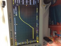
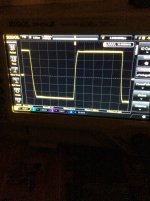
I had an overshoot problem using the 6pF compensation capacitor. To fix this I tried diferent value caps and the overshoot is gone at 10pF.
But the rising waveform looks funny. I attached a picture. Does the waveform is ok like this?
Thanks for your help.
Sorry I don't know why the pic is sidewise.
Hi,
I had an overshoot problem using the 6pF compensation capacitor. To fix this I tried diferent value caps and the overshoot is gone at 10pF.
But the rising waveform looks funny. I attached a picture. Does the waveform is ok like this?
Thanks for your help.
Sorry I don't know why the pic is sidewise.
Attachments
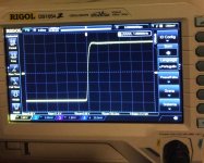
I don't see anything outright pathological there. Since the risetime of an amp is essentially the uncorrected error, it should be no surprise to see small waves in the large signal square wave response, especially from crossover harmonics or from the unique response curves for that particular amplifier. What would be disturbing is if there is a clear ringing and decay or if there are jerks at points along the wave.
As long as it drives a load without signs of oscillation there should be nothing wrong. I notice this amp doesn't have an output inductor, so the 10pF could make it more sensitive to loads. Try connecting a few different cables and see if it's stable when driving a load.
When you engineer an amp you generally go through a ring of tests to make sure your stability compensation works in all cases. This can take time. Generally the values are chosen with a good margin so small changes to values won't cause problems. If you have more 10pF caps I would use 2 in series to get much closer to 6pF. Then I would not be worried about stability.
When you engineer an amp you generally go through a ring of tests to make sure your stability compensation works in all cases. This can take time. Generally the values are chosen with a good margin so small changes to values won't cause problems. If you have more 10pF caps I would use 2 in series to get much closer to 6pF. Then I would not be worried about stability.
If you have more 10pF caps I would use 2 in series to get much closer to 6pF. Then I would not be worried about stability.
I have a 6pF capacitor but with it there is an overshoot in the rising edge. Then I tried 5.6pF, 6pF, 6.8pF, 8.2pF and then 10pF. The last one removed the overshoot. That's why I asked about the 10pF, all the others give me overshoot.
Are you saying the overshoot is not a problem?
Do you listen to over driven squarewaves?
")
I can't say it's my favourite music genre... I prefer jazz to square wavesDo you listen to over driven squarewaves?
If you want to adjust response behavior, use <1V square waves. Your large-signal square wave tests could be driving transistors out of normal operating points and causing spurious behavior that does not at all reflect what happens in response to actual music.
Did you substitute any transistors?
Did you substitute any transistors?
If you want to adjust response behavior, use <1V square waves. Your large-signal square wave tests could be driving transistors out of normal operating points and causing spurious behavior that does not at all reflect what happens in response to actual music.
Did you substitute any transistors?
No, I'm using 2SA970BL, 2SC2240BL matched, current sources and drivers are BC546/56
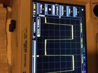
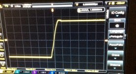
test with a range of slightly reactive loads.More pics
Are these pics normal?
Try 8r\\1nF, ||3n3F, ||10nF, ||33nF, ||100nF, ||330nF and maybe ||1uF, but by then you have probably gone way past the oscillation/bad ringing on a fast squarewave.
Also try 4r and 16r with the caps to see if the amp behaves differently.
You may need to trim back the RF attenuator on the amp's input. If it is set to <=100kHz then try moving it up by 1decade to ~1MHz.
That will still slow down the step from a pure squarewave.
- Home
- Amplifiers
- Solid State
- SKA GB150D now public domain...