Almost ready to assemble Spooky
My parts are almost here. Dale Vishay resistors from Israel, Phillips transistors from Bulgaria, Schroff chassis, Transformers from Avel Lindberg. I would like to know what builders are using for speaker protection: The New NEC UPC chip?? It would seem to me that no relay acts fast enough. Transformers put on + and - 63v. Who has the best deal on Sanken outputs? Thanks for the feedback. Has anyone heard from Pete and how he is doing? Ray
My parts are almost here. Dale Vishay resistors from Israel, Phillips transistors from Bulgaria, Schroff chassis, Transformers from Avel Lindberg. I would like to know what builders are using for speaker protection: The New NEC UPC chip?? It would seem to me that no relay acts fast enough. Transformers put on + and - 63v. Who has the best deal on Sanken outputs? Thanks for the feedback. Has anyone heard from Pete and how he is doing? Ray
My parts are almost here. Dale Vishay resistors from Israel, Phillips transistors from Bulgaria, Schroff chassis, Transformers from Avel Lindberg. I would like to know what builders are using for speaker protection: The New NEC UPC chip?? It would seem to me that no relay acts fast enough. Transformers put on + and - 63v. Who has the best deal on Sanken outputs? Thanks for the feedback. Has anyone heard from Pete and how he is doing? Ray
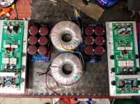
I'm running Jwilhelm and Vzaichenko's 21'st century protection board on my slewmasters. I use two mono blocks (+-70v) with spooky ips for subwoofers and a dual mono (with dual protection) KND (+-80V) for main speakers. The amp for the main speakers have been in daily use for two years now.
The protection system have saved my amps many times. i even shorted the speaker output once. Just had to reset the protection board and the amp continued playing music.
")
Slewmasters. one channel silent.
I took this step by step(as also advised from other members).Started with the OPS.
First the bulbletest with 15 kohm from V+ to VD+ and from V- to ND-. A weak light bulble. Offset 135 mV and a very low current through the emitter resistors. Promessing. With the 15 kohm resistors still in place I started up from the variac. Bias around 10mV on each emitter resistors. I did not tried to
increase the bias at this point. My conclusion: The OPS is "healty".
Also the IPS was started up with the bulble tester. OK. Then with the variac.
3.8 V was measured over both R12 and R13( both R19 and R10 had to be readjusted a little bit). Between PD+ and ND- I measured 12.4 V. Offset was now very close to zero.
So far as I can see, nothing wrong with my Slewmaster.
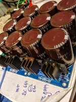
Next to examine:The loadspeaker protection. I noticed that both relais get hot when I placed my fingers on both of them. The other loadspeaker unit to the other channel did not behave the same way, and stayed cold.
What have went wrong with this loadspeaker protection, I do not. It is a cheap unit from China (see picture). Another unit will be ordered.
Eivind S
I took this step by step(as also advised from other members).Started with the OPS.
First the bulbletest with 15 kohm from V+ to VD+ and from V- to ND-. A weak light bulble. Offset 135 mV and a very low current through the emitter resistors. Promessing. With the 15 kohm resistors still in place I started up from the variac. Bias around 10mV on each emitter resistors. I did not tried to
increase the bias at this point. My conclusion: The OPS is "healty".
Also the IPS was started up with the bulble tester. OK. Then with the variac.
3.8 V was measured over both R12 and R13( both R19 and R10 had to be readjusted a little bit). Between PD+ and ND- I measured 12.4 V. Offset was now very close to zero.
So far as I can see, nothing wrong with my Slewmaster.
Next to examine:The loadspeaker protection. I noticed that both relais get hot when I placed my fingers on both of them. The other loadspeaker unit to the other channel did not behave the same way, and stayed cold.
What have went wrong with this loadspeaker protection, I do not. It is a cheap unit from China (see picture). Another unit will be ordered.
Eivind S
Attachments
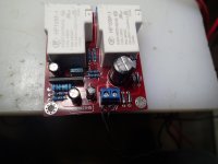
You must use DC power for those circuits! The controller chip and capacitors are probably very unhappy about the AC input.
You can run the relay at 24 volts. A small dropping resistor will correct the voltage if it is a little too high. You can expect that a 24 relay will work with 22 VDC applied without changes.
-Chris
You can run the relay at 24 volts. A small dropping resistor will correct the voltage if it is a little too high. You can expect that a 24 relay will work with 22 VDC applied without changes.
-Chris
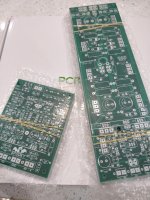
Slewmaster with 2pairs OPS Latfet
Hello to all Slewmaster experts,
since the slewmaster threads are so huge, a simple question.
Does there exist an OPS version with 2 TO3p pairs (2sk1058/2sj162) and the matching pcb or layout?
maximum supply voltage should be about 50- 54 volts!
pm for offers, pls
BR
Gunni
Hello to all Slewmaster experts,
since the slewmaster threads are so huge, a simple question.
Does there exist an OPS version with 2 TO3p pairs (2sk1058/2sj162) and the matching pcb or layout?
maximum supply voltage should be about 50- 54 volts!
pm for offers, pls
BR
Gunni
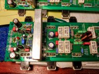
Guys, after very long time i decided restore this project....Just checking my errors... My question is about Q104, have to be mounted on heatsink together with Q103,107,108 ? Any reccomendation for IPS?
Attachments
Guys, after very long time i decided restore this project....Just checking my errors... My question is about Q104, have to be mounted on heatsink together with Q103,107,108 ? Any reccomendation for IPS?
Q104 has to be mounted on the main heatsink (under the board).
- Home
- Amplifiers
- Solid State
- SlewMaster Builds