Tried to fire up the CFA-x"h" that OS released long time ago.
OPS is the baby.
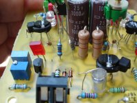
However when I connected the combo to my PS both 150r resistors on the ips cascode smoked.
I do not have a proper bench supply to slowly rise the operating voltage so I am not properly able to measure the voltages over these resistors.
Could someone give me a hint where to start the troubleshooting?
J
That resistor should be rated at least 1/2 watt, just check to be sure.
Edit - spook ... better bass , better psrr , durable - same fast slew - "whups " the VSSAI'm glad you like the "spook" ,Thimios. All the others are hung up on the
CFA's , LC thinks I'm a "spook" because I'm too poor to build now.
I did this all before ... built every IPS on the forum (except for the spook)
on my "Supersym thread".
I want to experience this IPS . Not to discount these CFA's , the spook
topology is often used for pro audio - it is TOUGH !
I have a V2 (TMC) spook that goes sub PPM ...
Let them build the CFA ... I really will "drop the VFA bomb" (with a
super refined layout) when I come back in july.
Super work ,Thimios ... (made in Greece) rules
Edit - spook ... better bass , better psrr , durable - same fast slew - "whups " the VSSA
I DO think the BV modded CFA-XH is nearly an equal (nearly - but not quite).
OS
I DO think the BV modded CFA-XH is nearly an equal (nearly - but not quite).
OS
I agree 100%!!!
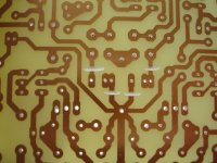
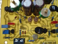
Now here is this CFA-X Ver.1.3.
Good work B.V!
Now this CFA may break the crystal and rock the floor!
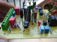
Some photos for easy modification.
Attachments
Last edited:
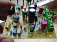
Used 22R /10W instead of fuses!With just one pair OUT installed you must read approx 1.5v on 22R.Use a lamp on the transformer primary side.Tried to fire up the CFA-x"h" that OS released long time ago.
OPS is the baby.
However when I connected the combo to my PS both 150r resistors on the ips cascode smoked.
I do not have a proper bench supply to slowly rise the operating voltage so I am not properly able to measure the voltages over these resistors.
Could someone give me a hint where to start the troubleshooting?
J
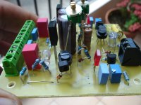
What is your power supply voltage?
Mine is +/- 50V and mine 150R are 1/4W without any problem(750mV) P=0.75*0.75/150=0.00375W
Check transistors position!
Attachments
Last edited:
Hello Thimios,
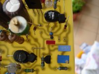
I too use 22r 5w instead of fuses. When powered the voltage drop over safety resistors is about 5v. This is way too high reading.
The rails are 50V on my test psu.
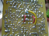
My first suspect are the cascode transistors, I need to desolder them and check that they are oriented correctly. It is just too bad that I glued those togehter!
The OPS work perfectly as standalone.
J
I too use 22r 5w instead of fuses. When powered the voltage drop over safety resistors is about 5v. This is way too high reading.
The rails are 50V on my test psu.
My first suspect are the cascode transistors, I need to desolder them and check that they are oriented correctly. It is just too bad that I glued those togehter!
The OPS work perfectly as standalone.
J
I try to remember to mark the top of one of the transistors before I glue them together and write down which one I marked. Been there, done that. If you plan to do a lot of diy audio, I highly recommend watching for a good deal on a variac. And,build yourself a lightbulb test circuit. I can't tell you how many times those two things have saved my butt. I never, ever start up a new circuit without them.
So you are referencing the input section clipping as the output sections are identical except for the feedback mode? How does the VFA clip better and where is the durability difference coming from?
The CFA "current on demand" makes the Hawksford saturate (different ?).
Both clip well , but the VFA would most likely be able to clip for 20 years
straight. Its not as "stressed" while clipping.
Spook topology was so popular in pro amps for a reason. Live show in
the 70/80's .. you were listening to a symmetrical VFA - not a CFA.
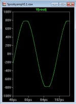
Observed signal on the spook clip is real nice rounded edges , almost
no "sharpies" (better for speakers -tweeters). Sort of a "soft clip".
CFA is still nice .... but more high order harmonics. If we don't clip ...
none of this is an issue . But , after a drink or two , abuse can occur
.OS
OS,
I was around Pro-audio in the 70's and 80's and have seen many smoked amplifiers, the passive crossovers and multi-enclosure systems stressed those amplifiers to no end. I was there with the first Spectra Sonic and Phase Linear amplifiers and believe me we pushed those to destruction many times doing outdoor concerts. There were many other amplifiers tried over those years and the important factors at that time seemed to be slew rate and output power. Sonic differences were very clear between different manufacturers whether the previous named or things like BGW and so many others. Many came and many went and many were far from bulletproof. clipping was a common occurrence during live shows and until many of the very high powered switch mode amplifiers became common this was just how things were.
I am not worried about the clipping output of your designs, as long as I select enough output pairs with matched power supplies I understand that by the time the amplifier is clipped the speakers will have been destroyed! I have been thinking of how I can set an absolute maximum input power level to avoid this situation. Basically a limiter on the input power from any attached device.
If your are clipping a +-80V Slewmonster your ears and speakers are going to be your biggest concerns.
I'm not quite the optimist.
I always consider the worst case.OS
Well clipping does occur on occasion to everyone, whether it be on purpose, ie turning it up too loud, or by mistake by sending some stupid signal through the loudspeakers. But in normal use I will never clip my amplifiers, I simply don't listen that loud and they are of reasonable sensitivity.
This can be solved very easy, if needed. It is no problem to avoid saturation in cascode and limit currents to safe levels (10-15mA), few added pasive components are enough. But if are "corners" rounded (soft clipping) or not, during hard clipping so big amount of power is shifted to higher harmonics (square wave spectra..) , that no one "normal" tweeter can survive it longer than few seconds.The CFA "current on demand" makes the Hawksford saturate (different ?).
Both clip well , but the VFA would most likely be able to clip for 20 years
straight. Its not as "stressed" while clipping.
So rounded corners during clipping are more psychologic phenomen (it" looks nice"), than something really needed. It is important to avoid sticking in limitation (and ensure fast recovery, no one active component should deep saturate) . And rounded corners means rising distortion far below clipping point.
. And rounded corners means rising distortion far below clipping point.
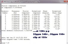
Strange ... THD wise , the spook holds on to low double digit PPM to nearly
full power
...(spook and sym are best in this metric) - 120v p-p+ with high rails.
OS
Attachments
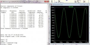
CFA-Xmod
Harmonic Frequency Fourier Normalized Phase Normalized
Number [Hz] Component Component [degree] Phase [deg]
1 2.000e+04 6.100e+01 1.000e+00 -1.92° 0.00°
2 4.000e+04 6.750e-04 1.106e-05 5.81° 7.73°
3 6.000e+04 7.656e-04 1.255e-05 78.92° 80.84°
4 8.000e+04 1.309e-04 2.146e-06 38.27° 40.19°
5 1.000e+05 7.082e-04 1.161e-05 -68.64° -66.72°
6 1.200e+05 1.376e-04 2.256e-06 45.18° 47.10°
7 1.400e+05 1.228e-04 2.012e-06 -29.53° -27.61°
8 1.600e+05 7.670e-05 1.257e-06 53.83° 55.75°
9 1.800e+05 2.559e-04 4.195e-06 -35.15° -33.23°
Total Harmonic Distortion: 0.002116% amplitude 160.2V p-p
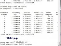
Harmonic Frequency Fourier Normalized Phase Normalized
Number [Hz] Component Component [degree] Phase [deg]
1 2.000e+04 6.154e+01 1.000e+00 -1.92° 0.00°
2 4.000e+04 6.406e-04 1.041e-05 13.80° 15.72°
3 6.000e+04 8.390e-03 1.363e-04 3.19° 5.11°
4 8.000e+04 2.163e-04 3.514e-06 -5.70° -3.79°
5 1.000e+05 7.932e-03 1.289e-04 -179.29° -177.37°
6 1.200e+05 2.367e-04 3.846e-06 105.10° 107.01°
7 1.400e+05 8.286e-03 1.346e-04 -6.49° -4.57°
8 1.600e+05 2.622e-04 4.261e-06 -22.58° -20.66°
9 1.800e+05 7.872e-03 1.279e-04 172.30° 174.22°
Total Harmonic Distortion: 0.026427% amplitude 160.3V p-p
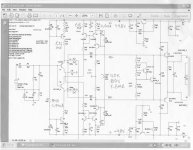
Amplitude change 0,1V p-p, distortion rise one order. Clipping picture attached.
Harmonic Frequency Fourier Normalized Phase Normalized
Number [Hz] Component Component [degree] Phase [deg]
1 2.000e+04 6.100e+01 1.000e+00 -1.92° 0.00°
2 4.000e+04 6.750e-04 1.106e-05 5.81° 7.73°
3 6.000e+04 7.656e-04 1.255e-05 78.92° 80.84°
4 8.000e+04 1.309e-04 2.146e-06 38.27° 40.19°
5 1.000e+05 7.082e-04 1.161e-05 -68.64° -66.72°
6 1.200e+05 1.376e-04 2.256e-06 45.18° 47.10°
7 1.400e+05 1.228e-04 2.012e-06 -29.53° -27.61°
8 1.600e+05 7.670e-05 1.257e-06 53.83° 55.75°
9 1.800e+05 2.559e-04 4.195e-06 -35.15° -33.23°
Total Harmonic Distortion: 0.002116% amplitude 160.2V p-p
Harmonic Frequency Fourier Normalized Phase Normalized
Number [Hz] Component Component [degree] Phase [deg]
1 2.000e+04 6.154e+01 1.000e+00 -1.92° 0.00°
2 4.000e+04 6.406e-04 1.041e-05 13.80° 15.72°
3 6.000e+04 8.390e-03 1.363e-04 3.19° 5.11°
4 8.000e+04 2.163e-04 3.514e-06 -5.70° -3.79°
5 1.000e+05 7.932e-03 1.289e-04 -179.29° -177.37°
6 1.200e+05 2.367e-04 3.846e-06 105.10° 107.01°
7 1.400e+05 8.286e-03 1.346e-04 -6.49° -4.57°
8 1.600e+05 2.622e-04 4.261e-06 -22.58° -20.66°
9 1.800e+05 7.872e-03 1.279e-04 172.30° 174.22°
Total Harmonic Distortion: 0.026427% amplitude 160.3V p-p
Amplitude change 0,1V p-p, distortion rise one order. Clipping picture attached.
Attachments
Last edited:
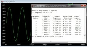
Ha ... ha ...
A contest ? Trying to trick me to show V2 "spook" w/ 5ppm at these levels.
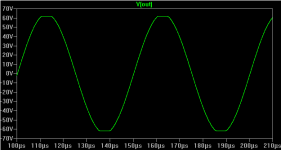
how about 230v p-p @ 22ppm ?
It looks like the "rumble" is between spook - CFA-Xh .
This is the "limit", 15V cascode + 120v to-92's (130V rails) !!
33 ppm <250v p-p)
OS
A contest ? Trying to trick me to show V2 "spook" w/ 5ppm at these levels.
how about 230v p-p @ 22ppm ?
It looks like the "rumble" is between spook - CFA-Xh
.This is the "limit", 15V cascode + 120v to-92's (130V rails) !!
33 ppm <250v p-p)
OS
Attachments
Last edited:
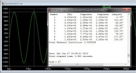
Bias too low on high level sim.
Only 35ma before at 22ppm.
Here's @ 220V p-p 20k with 77ma Ef bias.
.... ha ! (the VFA bomb).
Edit - with limited CLG , tmc only gives a 4X thd reduction on the spook.
Higher CLG wolverine ... 10X +
OS
Only 35ma before at 22ppm.
Here's @ 220V p-p 20k with 77ma Ef bias.
.... ha ! (the VFA bomb).Edit - with limited CLG , tmc only gives a 4X thd reduction on the spook.
Higher CLG wolverine ... 10X +
OS
Attachments
Last edited:
have no interest on contest, no with simulation, reality is what counts. You wrote
What is "nearly"? 1V, 5V 10V under clipinng? Or 0.1V ? That is what i mean with "far below"..to nearly full power
I'm sure ,you have this VFA bomb.Only 35ma before at 22ppm.
Here's @ 220V p-p 20k with 77ma Ef bias.
Edit - with limited CLG , tmc only gives a 4X thd reduction on the spook.
Higher CLG wolverine ... 10X +
OS
Spooky is the light ver. of this.
Hi Juan go ahead and make a PCB for CFA with all recommended by BV modifications.OS have the problems now,he is under great pressure
Last edited:
have no interest on contest, no with simulation, reality is what counts. You wrote
What is "nearly"? 1V, 5V 10V under clipinng? Or 0.1V ? That is what i mean with "far below"..
3V (below 29ppm 250V p-p) ,
254V = 60ppm ...
clip is 255v.
Both hawksfords should react the same near the "threshold".
Still , more than adequate performance - layout will determine the final result.
I was joking about "contests" ... you know.
There ... mine is longer
.PS - thinking about the CFA/VFA differences , CFA might allow the "threshold"
to be even closer to the rails - but at 100's of volts ..... ???
OS
Attachments
Last edited:
- Home
- Amplifiers
- Solid State
- Slewmaster - CFA vs. VFA "Rumble"