Terry,
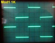
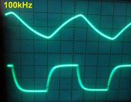
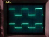
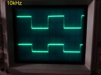
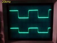
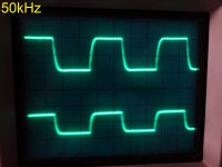
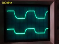
One thing that is confusing me are the lower posted scope shots. Aren't they both of the same signal generator? If this is just the signal generator output why don't they look the same in both sets of measurements? I can see even without zooming in that the traces are different at the leading edge with what looks like a slight peak on the first set of traces.
Dv/Dt what this is saying Terry if I am no idiot is the rate of voltage rise over time. How fast the amplifier can produce a voltage rise vs the time to do it. Really a simple division problem. Voltage over time.
Hi Kind,
When I was first seeing these square waves I tried bypassing the input cap to see if that would help. I forgot to remove the jumper before I took those readings. Here are some shots with the input cap in circuit.
It would be nice to find how to fix this. My DX Super A has a very similar wave shape.
Blessings, Terry
Attachments
Terry,
I may have missed it but have you changed the caps that OS suggested?
"Not really that bad. No sustained oscillation ... raise Cdom(s) to 47p.
Bonsai's NX needed 47p to quench the "ring" (his nx pdf explains).
PS -The nx has the same ...but a "mono" MIC comp.
OS"
I may have missed it but have you changed the caps that OS suggested?
"Not really that bad. No sustained oscillation ... raise Cdom(s) to 47p.
Bonsai's NX needed 47p to quench the "ring" (his nx pdf explains).
PS -The nx has the same ...but a "mono" MIC comp.
OS"
Thanks Terry,
The square waves look better now than in post #2875, that was making me wonder what was going on. Glad Jason's description made that picture in your head for the slew rate. I forget the number but there is a minimum slew rate that is supposed to be enough to cover the entire audio bandwidth but many find that it isn't really enough. Not sure at what point of diminishing returns it just becomes an exercise like ppb distortion #'s.
The square waves look better now than in post #2875, that was making me wonder what was going on. Glad Jason's description made that picture in your head for the slew rate. I forget the number but there is a minimum slew rate that is supposed to be enough to cover the entire audio bandwidth but many find that it isn't really enough. Not sure at what point of diminishing returns it just becomes an exercise like ppb distortion #'s.
Hi Kind,
Yes better but not good.
Jason,
Yes, this is built on the schematic I attached in post #2865 above. I have been looking at the newest one BV posted. It can be done of these boards but I need to work on it a little more. BV says the layout is more critical and with the troubles I'm having with this circuit I'm not sure if it is worth the trouble. If we get this one working properly, I will try the other. No sense in you making gerbers for a circuit that doesn't work.
Carl,
No I haven't made the changes that OS suggested because I don't know what the Cdom is. I will need part numbers.
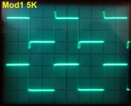
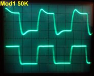
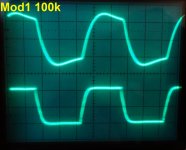
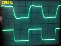
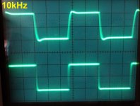
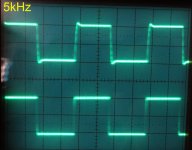
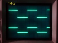
OK screen shots with 47p installed in CM1 an CM2. Different, but better? Still not as clean as unmodified CFA XH.
Attachments
I'd say that #2882 looks better than what you are getting now, at least a semblance of a sq. wave at 50khz
Yes, but the unmodified CFA-XH in #2876 looks tons better. Something is just not right.
Make the gain equal on the mod ... and see what the result is.
This will determine whether it is just a phase margin issue or some
other issue.
68/2.7k on the mod gives the same 26db gain as 100/2.7k on the
original.
OS
2 feedback resistor must change to 2x from original value to get same gain if we use BV compensation.
BV,
I had similar issues with the Super A and I remember you making statements about errors in the circuit. See here. http://www.diyaudio.com/forums/solid-state/221741-dx-blame-st-together-dx-super-25.html#post3696909
I don't mind trying new things. I have extra boards and the parts are cheap for these IPS but I don't learn anything useful if solutions are not found. The Super A actually sounds very good in spite of the overshoot. I haven't tried playing music through this one. Probably sounds fine. I just don't understand the purpose of changing the circuit if it is not improved. Obviously, simulations don't tell the whole story.
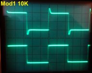
I allow to think someone overlooked above.Square waves pictures looks simply like well damped overshoot (the same duration in all pictures), at inductive load and/or output inductor, or inductance (parasitic -e.g. wires between IPS and OPS) somewhere in circuit, SR is quite high (dU/dT). Try to place paralel to output inductor second resistor, 5-10ohm. If peak will decrese, it is clear. Amp wit lower SR will not show this behavior. Or increase input filter capacity.
Stillforgiven problem seems after IPS, confirmed by you tested IPS with perfect square waves.
Something from after IPS can't keep up with higher SR. BV mention wires or output inductor in OPS. Try his 5-10ohm suggestion parallel to that output inductor to get speed up again. Last he suggest increase input filter (the small xx-pF cap going to ground in input just after a small serial resistor. As i see because IPS tested positive, have concentration on wiring from there to load connection at OPS, and only increase input filter if nothing else will do.
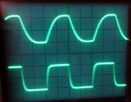
OK so I have my donkey ears on today. Great job OS deducing the problem. I pulled what I thought was a 50R only to find an 11.1R. I'm not sure where that came from. I thought I was careful to measure every resistor before I installed it. Anyway, I installed a 68R and everything looked pretty good except the most I could get out of the amp with a 1.2Vac input all I could get was 21Vac out so I replaced it with a 47R. Now I can get 41vac output. I remember earlier remarking how high the gain on this amp was compared to the CFA. Now I know why.
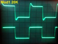
Anyway, all that to say that fixed the overshoot. Square waves look beautiful. I reinstalled the 33p also because the squarewaves are better looking than with the 47P See attached.
Blessings, Terry
Anyway, all that to say that fixed the overshoot. Square waves look beautiful. I reinstalled the 33p also because the squarewaves are better looking than with the 47P See attached.
Blessings, Terry
Attachments
") Troubleshooting can sometimes be a right pain in the behind and very frustrating.
Troubleshooting can sometimes be a right pain in the behind and very frustrating.- Home
- Amplifiers
- Solid State
- Slewmaster - CFA vs. VFA "Rumble"