Thanks,it is very kind of youThimios,
English may not be your first language but I must say it is very easy for me as an English speaker to understand what you write. I think you English is very strong for a non native speaker.
")
Ok Boss i will try this today.Thimios , I want to wrap this up.
Try the different CCS to make it thermally stable.
Half this amp is the NAD/NX CFA. That one would stabilize because in/NFB
cancelled. This is a full bridge , no such cancellation is native to it.
But , the "2Q" seems to be just the right amount of thermal cancellation.
OS
I have put there a 2x22R(parallel) /5W but i haven't any non inductive resistor except some 0.22-0.47R/5WJust add a non inductive resistor parallel over your output inductor,
I have sometimes made the coil by winding 15 or so wraps of Teflon isolated 1 mm solidcore over a 4 ohm 10W non inductive resistor.
Last edited:
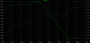
If i well understand we are on the right way.A feedback amplifier has an inductive output impedance. The better the amplifier, the higher the Q of this inductance. A good amplifier will ring for longer with a capacitor at the output.
To prevent this requires putting some lossy component between the amplifier and capacitor. The L//R network qualifies, but making it large enough to permanently eliminate resonance with capacitors would add too much resistance between the amplifier and load.
Bottom line. if you amp resonates or has overshoot with a capacitor on the output, it's a GOOD thing. It means the feedback is working well. It's not the amp that's the problem, it's your load.

Yes but not now ,give me some time.thimios can you perform the test with the 0.68uF cap for Kypton -C and Kypton -V and post pictures?
Thimios , I want to wrap this up.
Try the different CCS to make it thermally stable.
Half this amp is the NAD/NX CFA. That one would stabilize because in/NFB
cancelled. This is a full bridge , no such cancellation is native to it.
But , the "2Q" seems to be just the right amount of thermal cancellation.
OS
Unfortunately this isn't useful .
We have the same issue.
Os did you see what i mentioned.Reason for thermal instability isn't CCS but Q5,Q6,Q7,Q8.
Touching these, VAS current vary in a long way.
Attachments
Last edited:
Yes but not now ,give me some time.
ok.thank you!!
Unfortunately this isn't useful .
We have the same issue.
Os did you see what i mentioned.Reason for thermal instability isn't CCS but Q5,Q6,Q7,Q8.
Touching these, VAS current vary in a long way.
But the CCS should give less current as the WHOLE IPS heats up ?
(offsetting the increased current of Q5-8).
If you use a hot hair dryer , or put amp in the freezer .... does it stay
about the same ?
Touching just the ONE stage (Q5-8) should make for a current change.
OS
Last edited:
Look OS .But the CCS should give less current as the WHOLE IPS heats up ?
(offsetting the increased current of Q5-8).
If you use a hot hair dryer , or put amp in the freezer .... does it stay
about the same ?
Touching just ONE stage should make for a current change.
OS
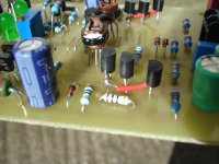
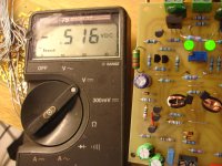
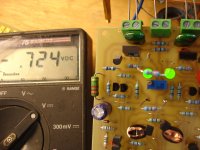
When the ampl.is powered on, the measurement on R24 or R31=390mV
After about 5 minutes the measurement on R24 or R31=780mV.
When you touch Q5 or Q6 or Q7 or Q8 your measurement quickly going down 600,500,400 etc.
Last edited:
I will try this and report .Thimios , Touch the 3(6) CCS semi's .... current should go down.
OS
.....Touching Q5,Q6,Q7,Q8 VAS current vary in a long way
Haven't got a clue if this can help but is those the ones with copper wrapped around, because If remembering correct over the PeeCeeBee thread one member had fluctuation when a piece of alu was wrapped around input pair and think it was healed by grounding the metal or remove it leaving only the plastic pressure strip.
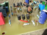
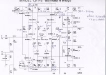
Please OS look at this.
Where is (st)symbol voltage is stable
Where is (v) symbol voltage vary.
Touching the CCS tran.no effect.
Touching all other tran.no effect.
Touching Q5,Q6,Q7,Q8 VAS current vary in a long way
In the Infidel design the trailing transistors in the diamond buffers (Q5,6,7,8) dissipate a much higher power than their associated leading transistors (Q1, 2, 3, 4), and they are not thermally coupled in the PCB design in order to cancel out or balance the Vbe changes, due to the Vbe tempco, between a leading transistor and its trailing brother. As a result, a warm up period is anticipated for the transistors to arrive at a stable individual temperatures, hence the changing collector current at trailing transistors and the VAS standing current at starting up.
If a much shorter ramp-up time is desired, there could be a couple quick ways to do it.
1) thermally coupling the leading and trailing transistors, Q1-Q5, 2-7, 4-6, 3-8. Unfortunately it's not easy as the transistors are distance apart in the PCB layout.
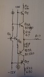
or 2) cascoding the trailing transistors at +/-12V rails to reduce their operating Vce to greatly cut down their power dissipation, or temperature rise, therefore, reducing the time needed for them to come to a stable temperature. This would only require two more BC550 and two more BC560 to be uses as trailing traqnsistors. The KSC1845/KSA992 currently being used at Q5-8 can be re-wired as the cascoding transistors. As shown in the picture, Q5A and Q7A are the newly added transistors.
Attachments
Thimos
To make it solid you need to make a new PCB, where the 4 transistors making the two input diamonds and the two biasing transistors in the CCS feeding the diamond, must be thermally coupled and thus placed close on the PCB, this way you'll get stable currents that don't drift. This is how I have been doing it on my various CFA's and the very reason why I keep advocating good housekeeping,
To make it solid you need to make a new PCB, where the 4 transistors making the two input diamonds and the two biasing transistors in the CCS feeding the diamond, must be thermally coupled and thus placed close on the PCB, this way you'll get stable currents that don't drift. This is how I have been doing it on my various CFA's and the very reason why I keep advocating good housekeeping,
Last edited:
or 2) cascoding the trailing transistors at +/-12V rails to reduce their operating Vce to greatly cut down their power dissipation, or temperature rise, therefore, reducing the time needed for them to come to a stable temperature. This would only require two more BC550 and two more BC560 to be uses as trailing traqnsistors. The KSC1845/KSA992 currently being used at Q5-8 can be re-wired as the cascoding transistors. As shown in the picture, Q5A and Q7A are the newly added transistors.
This exactly how I do in my 200W mosfet amp.
Natawa, what is going on with your smd layout for VMOSFET amp, did you build it?
Damir
This exactly how I do in my 200W mosfet amp.
Natawa, what is going on with your smd layout for VMOSFET amp, did you build it?
Damir
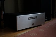
Dadod, I'm in the middle of building my Meistersinger VFA and haven't started the 200W VMOSFET CFA. I had 2nd thoughts about the VMOSFET being without EC and may decide to build your TT-OIC version first instead, based on a similar SMD PCB layout design to the VMOFET one. I have had all the TT transistors in hand. This is the metal work I've just finished. The wife wants a Finished job for our living room, so a lot of effort spent on the metal work. The CFA will have the identical chassis.
Sorry for the slight OT.
Attachments
Thimos
To make it solid you need to make a new PCB, where the 4 transistors making the two input diamonds and the two biasing transistors in the CCS feeding the diamond, must be thermally coupled and thus placed close on the PCB, this way you'll get stable currents that don't drift. This is how I have been doing it on my various CFA's and the very reason why I keep advocating good housekeeping,
I fully understand.
As I see it , it have 2 choices for complexity.
1. "Muntz" it,make both the bridge and diamonds high Vce (no 12V supply).
2. Add 4 cascodes (for 20 devices) , keep my 12 supply.
Either way , i will still have to couple CCS to diamond ... right ?
Or , was that - bridge to diamond ?
I'll sim both. BTW, the simulator did not show this with the thermal
.step command..
OS
- Home
- Amplifiers
- Solid State
- Slewmaster - CFA vs. VFA "Rumble"