Ostripper, cascodes will make The effect less likely to escalate into the OPS, but it's still there, if you use the same transistors for input transistors and for the bias spread in the CCS, then thermals will cancel almost completely. I even prefer to mirror the currents over into the VAS, this gives even better tracking and lower distortion (esp higher orders)
Ostripper, cascodes will make The effect less likely to escalate into the OPS, but it's still there, if you use the same transistors for input transistors and for the bias spread in the CCS, then thermals will cancel almost completely. I even prefer to mirror the currents over into the VAS, this gives even better tracking and lower distortion (esp higher orders)
Even as I am not afraid of 20 devices , my social "study" of these IPS's show
that sub 16 device ones are the most likely actually built.
That is as much a reason for the CFA success as the reported sound -simplicity.
Look (below) , if I go simple with all Ksc1845/ksa992's ... would I
thermally couple CCS-diamond or bridge-diamond ?
I'll even leave the option of 2Q or LED CCS to allow for different
co-efficient's.
OS
Attachments
Thimios could try this ....
On his existing board.
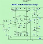
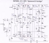
Just replace diamonds(Q1-4) with 1845/992's (watch pinout). Get rid of
the zener and jumper it's dropping resistor. Review below schema.
We could see first , if having the same devices for both diamonds/bridge
will reduce the thermals.
With the exact same devices for both diamond/bridge , they should track
each other perfect - same Vce/same current. (below 1).
Now , on to the coupling of diamonds/CCS (below 2). Miib , you said
couple the 6 (CCS speaders/diamonds) - spreaders are Q5/8 in this
schema.
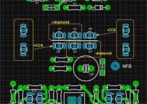
Copper or aluminum sheet across all 6.
OS
On his existing board.
Just replace diamonds(Q1-4) with 1845/992's (watch pinout). Get rid of
the zener and jumper it's dropping resistor. Review below schema.
We could see first , if having the same devices for both diamonds/bridge
will reduce the thermals.
With the exact same devices for both diamond/bridge , they should track
each other perfect - same Vce/same current. (below 1).
Now , on to the coupling of diamonds/CCS (below 2). Miib , you said
couple the 6 (CCS speaders/diamonds) - spreaders are Q5/8 in this
schema.
Copper or aluminum sheet across all 6.
OS
Attachments

Last edited:
Thanks all for reply.On his existing board.
Just replace diamonds(Q1-4) with 1845/992's (watch pinout). Get rid of
the zener and jumper it's dropping resistor. Review below schema.
We could see first , if having the same devices for both diamonds/bridge
will reduce the thermals.
With the exact same devices for both diamond/bridge , they should track
each other perfect - same Vce/same current. (below 1).
Now , on to the coupling of diamonds/CCS (below 2). Miib , you said
couple the 6 (CCS speaders/diamonds) - spreaders are Q5/8 in this
schema.
Copper or aluminum sheet across all 6.
OS
If i have a970 (sure i have c1845)i will try the first modification today.
Second modification is imposible to fit on existing pcb.
Keep in mind that i has try to thermal couple Q5.Q6,Q7,Q8 all together but this isn't useful.
Problem isn't the slow current rise but the unstable current because of thermal condition changes.
When air blow on these Q5-Q8 VAS current fall dramatically
Last edited:
Thimios , I want to wrap this up.
Try the different CCS to make it thermally stable.
Half this amp is the NAD/NX CFA. That one would stabilize because in/NFB
cancelled. This is a full bridge , no such cancellation is native to it.
But , the "2Q" seems to be just the right amount of thermal cancellation.
OS
Os you shouldnt call this design a bridge at all, because it isnt. The H bridge topology is something quite different. This topology is simply known as a voltage amplifier designed with current feedback principles. True bridge topology was invented and patended by Gosser from Analog Devices 20 years ago and is a different design altogether. What you have here predates it by another 5 years. Research the Gosser patent and youll see its much different.
I fully understand.
As I see it , it have 2 choices for complexity.
1. "Muntz" it,make both the bridge and diamonds high Vce (no 12V supply).
2. Add 4 cascodes (for 20 devices) , keep my 12 supply.
Either way , i will still have to couple CCS to diamond ... right ?
Or , was that - bridge to diamond ?
I'll sim both. BTW, the simulator did not show this with the thermal
.step command..
OS
Try 2 different step commands simultaneously if possible.One concerning temperatures of Q1,Q2,Q4,Q3 and the other concerning temperatures of Q5,Q7,Q6,Q8.
Otherwise keep temperature of Q1,Q2,Q4,Q3 constant and step that of
Q5,Q7,Q6,Q8.
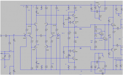
This thermal "unstability" (positive coeficient) is caused in bridge, Q11-Q14. Voltage between bases Q11/Q13 and Q12/Q14 is dropping with raising temperature (current thru Q1-Q4 is stable ,given by CCS, but Vbe is dropping with raising temperature) , but dropping Vbe treshold in Q11-Q14 will overdrive this negative input thermal cowficient, because R14, R15, R19, R20 are too low, so Ic in bridge will raise with temperature.
Is .asc file for "infidel" available?
Is .asc file for "infidel" available?
This thermal "unstability" (positive coeficient) is caused in bridge, Q11-Q14. Voltage between bases Q11/Q13 and Q12/Q14 is dropping with raising temperature (current thru Q1-Q4 is stable ,given by CCS, but Vbe is dropping with raising temperature) , but dropping Vbe treshold in Q11-Q14 will overdrive this negative input thermal cowficient, because R14, R15, R19, R20 are too low, so Ic in bridge will raise with temperature.
Is .asc file for "infidel" available?
I'm kind of "lost" as to where Thimios's prototype can differ from my sim.
So, here it is. Thanks !
OS
Attachments
Last edited:
I think Thimios should drop the LED current source and use a dual transistor CCS instead.
Why?
Please this schematic is small we can't see well.2 ostripper
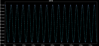
Temperature stepped 25,50,75,100 grade..
If it's possible post a more clear bigger one.
I see that no CCS recommended by BV
Thanks.
Thimios.
Last edited:
asc file
This kind of temperature simulation is not very useful, the temperature was changed for whole amp and that is not real thermal behavior. Better change temperature for particular transistors to see thermal dependences.
- Home
- Amplifiers
- Solid State
- Slewmaster - CFA vs. VFA "Rumble"