Your supply boards are packaged up and ready to ship already. I wonder what's going to happen with shipping over Christmas.
You have that little Asian workshop in your backyard ? !!

22'nd Nah .... told my wife the "cutoff" for online goods was last
week .... (for Xmas presents) .
OS
jwhilhelm,
Sounds like we have both had our share of machining experiences. There have been times when we have had aluminum heat treated to make it dead soft, annealed so we could form it, but it doesn't stay in that soft condition long before it reverts to a harder material. My tool and die workers hated working with titanium, that was not fun. We were one of a few companies that formed and precision ground titanium leading edges for helicopter rotor blades. Stainless is always an accident waiting to happen, one bad chip and your toast. I love it when I see someone putting a stainless nut on a stainless bolt without any anti-seize and spins it on fast, good luck ever getting that apart if it actually tightens up before seizure. Machining is fun isn't it.
Sounds like we have both had our share of machining experiences. There have been times when we have had aluminum heat treated to make it dead soft, annealed so we could form it, but it doesn't stay in that soft condition long before it reverts to a harder material. My tool and die workers hated working with titanium, that was not fun. We were one of a few companies that formed and precision ground titanium leading edges for helicopter rotor blades. Stainless is always an accident waiting to happen, one bad chip and your toast. I love it when I see someone putting a stainless nut on a stainless bolt without any anti-seize and spins it on fast, good luck ever getting that apart if it actually tightens up before seizure. Machining is fun isn't it.
Aluminium is a very soft metal, but *immediately* oxide itself in contact with air. And, as previously said this oxide is very hard.
It can seems strange that this metal, one of the most prompt to oxide, is one that oxidize the less. It is just that the thin AL2O3 layer is waterproof and airtight, preventing oxygen to penetrate deeper.
But put a drop of mercury on aluminum, and see what happens;-)
It can seems strange that this metal, one of the most prompt to oxide, is one that oxidize the less. It is just that the thin AL2O3 layer is waterproof and airtight, preventing oxygen to penetrate deeper.
But put a drop of mercury on aluminum, and see what happens;-)
Last edited:
jwhilhelm,
Sounds like we have both had our share of machining experiences. There have been times when we have had aluminum heat treated to make it dead soft, annealed so we could form it, but it doesn't stay in that soft condition long before it reverts to a harder material. My tool and die workers hated working with titanium, that was not fun. We were one of a few companies that formed and precision ground titanium leading edges for helicopter rotor blades. Stainless is always an accident waiting to happen, one bad chip and your toast. I love it when I see someone putting a stainless nut on a stainless bolt without any anti-seize and spins it on fast, good luck ever getting that apart if it actually tightens up before seizure. Machining is fun isn't it.
I'm always building odd custom vehicles. I built an offshore race boat a few years ago so there was loads of stainless and aluminum machining there. I quickly learned the value of stepping up to 316L stainless. Whenever possible I choose a different metal to thread with stainless. Heat doesn't transfer through it so heat generated due to friction turns it molten quickly. Threading it to a different metal allows some cooling on assembly.
My only experience with titanium is welding dirt bike exhaust system. I actually don't like the metal. It seems to work harden quickly and fails miserably shortly after. Much like chrome moly but much more extreme.
My problems with aluminum temper goes the other way. I use 5056 or 3003 if I need to form it. Sounds like you were working on aviation parts so that wouldn't have been an option for you. When welding it goes dead soft, then machining the mush after isn't pleasant. It makes for poor finish cuts and aluminum sticking to everything.
Once Aluminum was more valuable than Gold
To impress dinner guests, Napoleon III’s tables were set with tableware made from aluminum. And as late as the 1880s, when the Washington Monument was being built and aluminum was chosen for the pyramid’s capstone, the metal’s worth was still roughly equivalent to silver.
Now we throw it in the trash or recycle it for pennies.
That's how they make XTC.[...]
But put a drop of mercury on aluminum, and see what happens;-)
krisfr,
I think if not for the fact that so much aluminum is recycled you would not see aluminum at such low prices. It is still rather expensive to process the raw ore with those large electric smelters from raw but from recycled it is rather inexpensive. It is nice that so many actually recycle this metal otherwise we would all be paying much more for this material.
I think if not for the fact that so much aluminum is recycled you would not see aluminum at such low prices. It is still rather expensive to process the raw ore with those large electric smelters from raw but from recycled it is rather inexpensive. It is nice that so many actually recycle this metal otherwise we would all be paying much more for this material.
Has anyone worked on an OPS bias like this or similar --- reducing Class AB switching distortion ??
View attachment OPS Bias.pdf
THx-RNMarsh
View attachment OPS Bias.pdf
THx-RNMarsh
I have a question here about class A, AB and B. If an amplifier is typically used above the limited Class A range wouldn't there be an advantage to running the amplifier in pure Class B rather than A/B? Doesn't that remove the switching mode noise that is so often spoken of forcing the amplifier to operate in Class B? Always trying to learn more here, hope this is not to off topic.
1st one in 5 years.
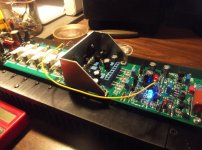
Wolverine works ! (below).
With no pot adjustmants,drivers were 1.25V across the 150R ... offset was .5mv.
Little CCS was 2.4 ma and the VAS CCS was 5.25ma.
VAS has NO heat @ 5.25ma. (do I really need a heatsink ?)
It's nice for VFA's , don't have to test with outputs (2 -1K's to NFB).
Spice estimated 25 and 21mA driver/IPS current draw. Real world is 25 /22ma.
From 10C outside to 25C inside both CCS's and drivers measured the same.
OS
Attachments
Has anyone worked on an OPS bias like this or similar --- reducing Class AB switching distortion ??
View attachment 455335
THx-RNMarsh
It is practically the same as a BJT output stage, which is two Vbe diodes with a constant voltage across them. The diodes themselves may be slower than a typical power BJT, or maybe faster.
One difference is that in a BJT output stage, the diodes have resistors in series to prevent thermal runaway.
That schematic can't be built as it is, because the diode Vf and bias controller Vbe will not have a repeatable offset.
Last edited:
I have a question here about class A, AB and B. If an amplifier is typically used above the limited Class A range wouldn't there be an advantage to running the amplifier in pure Class B rather than A/B? Doesn't that remove the switching mode noise that is so often spoken of forcing the amplifier to operate in Class B? Always trying to learn more here, hope this is not to off topic.
I may be a little off here but I think an AB amplifier is biased into class A just enough to remove crossover distortion at idle. There is no distortion when it switches out of class a to class B. It does this in every voltage swing of the signal.
Wolverine works ! (below).
With no pot adjustmants,drivers were 1.25V across the 150R ... offset was .5mv.
Little CCS was 2.4 ma and the VAS CCS was 5.25ma.
VAS has NO heat @ 5.25ma. (do I really need a heatsink ?)
It's nice for VFA's , don't have to test with outputs (2 -1K's to NFB).
Spice estimated 25 and 21mA driver/IPS current draw. Real world is 25 /22ma.
From 10C outside to 25C inside both CCS's and drivers measured the same.
OS
Looks like you forgot output devices! I've been wondering about heat sinks on the VAS too. If that's your sub amp they will need to be anchored to something if you do install them or the legs will break eventually on the transistors. That's why I came up with those for the Symasuis.
Looks like you forgot output devices! I've been wondering about heat sinks on the VAS too. If that's your sub amp they will need to be anchored to something if you do install them or the legs will break eventually on the transistors. That's why I came up with those for the Symasuis.
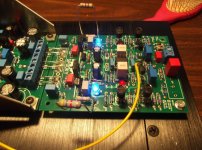
Who needs outputs ? Nice headphone amp !
Actually , to omit the outputs and bias the drivers to exactly 1.1V across Re will
bias any outputs added later to <10ma.
Now that that OPS is tested ... I can plug spooks into it. The tested wolverine
can be plugged in to all the other OPS's , as well.
OS
Who needs outputs ? Nice headphone amp !
Actually , to omit the outputs and bias the drivers to exactly 1.1V across Re will
bias any outputs added later to <10ma.
Now that that OPS is tested ... I can plug spooks into it. The tested wolverine
can be plugged in to all the other OPS's , as well.
OS
How do you make the feedback circuit operate? Jumper the base to output?
2 - 1k's from each side of the 150R driver resistor -> back to NFB.
Then , adjust driver bias to 1.1V across the 150R. NO chance of a blown output.
Hook a cap /47R in series out to a set of headphones . Amp (IPS) tested.
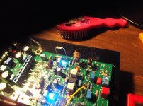
Just got the spooks running (Below) - thought I messed up (zener resistors) .. lower
voltage = 2K instead of 4.7k.
3.2ma CCS's exactly gets .95V on the VAS Re (6.3ma) ... but minus the 1ma
hawksford led I. .
CCS trimmers are reversed - one CC , one CW to increase current.
Servo settles better if you do this trick. If it comes from the negative side - reduce the
negative CCS a little. Settles in <1 sec.
PS - put these in the freezer , too. within .2ma -10C to 25C
OS
Then , adjust driver bias to 1.1V across the 150R. NO chance of a blown output.
Hook a cap /47R in series out to a set of headphones . Amp (IPS) tested.
Just got the spooks running (Below) - thought I messed up (zener resistors) .. lower
voltage = 2K instead of 4.7k.
3.2ma CCS's exactly gets .95V on the VAS Re (6.3ma) ... but minus the 1ma
hawksford led I. .
CCS trimmers are reversed - one CC , one CW to increase current
.Servo settles better if you do this trick. If it comes from the negative side - reduce the
negative CCS a little. Settles in <1 sec.
PS - put these in the freezer , too. within .2ma -10C to 25C
OS
Attachments
Last edited:
Got all the "bugs" out.
Well ... almost (below). And blew up one of my IPS's. Spooky with no IPS ground = fried TL072 servo. Thats it ! 1845/992's are high voltage , servo is not . All 4 OPS's and 3 IPS's - perfect , easy .... who designed this stuff ?? OS
Well ... almost (below). And blew up one of my IPS's. Spooky with no IPS ground = fried TL072 servo. Thats it ! 1845/992's are high voltage , servo is not . All 4 OPS's and 3 IPS's - perfect , easy .... who designed this stuff ?? OS
Attachments
- Home
- Amplifiers
- Solid State
- Slewmaster - CFA vs. VFA "Rumble"