I agree ... I'll add a couple resettable breakers to my tester. But for an amp
that has a cover and is not excessively "tinkered with" - just AC ... and rail
fuses should suffice.
Some in the audio world think fuses will actually detract from sound - the
twin 800VA Genesis had no DC fuses whatsoever ... with 10GA "oxygen free"
hookup wires.
OS
that has a cover and is not excessively "tinkered with" - just AC ... and rail
fuses should suffice.
Some in the audio world think fuses will actually detract from sound - the
twin 800VA Genesis had no DC fuses whatsoever ... with 10GA "oxygen free"
hookup wires.
OS
I actually watched fuse distortion on my test rig last week. I had a couple 1 amp rail fuses installed. It looked like clipping on the positive rail only with a sine wave going. The fuse was just starting to go liquid at the peak, then solidifying again on the negative swing. Cool to see!
I actually watched fuse distortion on my test rig last week. I had a couple 1 amp rail fuses installed. It looked like clipping on the positive rail only with a sine wave going. The fuse was just starting to go liquid at the peak, then solidifying again on the negative swing. Cool to see!
High Z - liquidification / low Z = solidification ....wild !!
OS
I've always been taught that fusing belongs at the source. Fuse again where it splits for distribution. But then again quite a few things are different in audio than the rest of the electrical world.
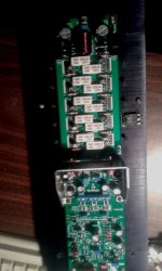
If the fuse was big enough for both channels, then it may be too big to blow in the occurrence of a failure in just one of the channels. The output PCB is just a convenient place to put the fuse holders.
That is why it is traditional to have rail fuses on each amplifier PCB. It would be slightly safer to place a bank of fuses immediately after the PSU, but most designers assume there won't be anyone around stabbing the wiring with a screw driver.
In the board I'm laying out there will be individual fuses for each amp module. Like a power distribution module on the board. I may just make up a standalone distribution module too. Still undecided. I like the way Jason did the output on his Mr Evil Cap Multiplier board. I may do that as well. http://www.diyaudio.com/forums/powe...pmi-capacitance-multiplier-6.html#post4098244
What was the frequency, for you where able to see-it, <10Hz ?Cool to see!

What was the frequency, for you where able to see-it, <10Hz ?
I was seeing it at a bunch of frequencies and input voltages. It took a bit to figure out what was going on. I thought I had damaged an input transistor at first. Then I remembered what I'd put in for fuses. The positive fuse was discoloured and the filiment was sagging.
"nothing but a DOUBTER " (polar express film)
You don't believe !! (below)
Fuses glow ... sometimes they can glow for a few seconds before failure.
seen it.
OS
I'll have to see if I can duplicate the fuse distortion with the office lights off and see if I can get the fuse to glow.
My question was about "The fuse was just starting to go liquid at the peak, then solidifying again on the negative swing. Cool to see!" with the inertia of the thermal effects and the 50 (or 60Hz ) remanence of the eyes."nothing but a DOUBTER " (polar express film)
You don't believe !! (below)
Fuses glow ... sometimes they can glow for a few seconds before failure.
seen it.
Of course i have seen many fuses in different states, including very hot or blowing in front of my eyes. But i was never able to follow their instant changes following a constant sinusoidal signal, reason of my question.
It is obvious that fuses are to be avoided in the rail path of any hifi amplifier, once the first test have been done. There is better and faster ways to protect amps and enclosures (see my signature ;-).
My question was about "The fuse was just starting to go liquid at the peak, then solidifying again on the negative swing. Cool to see!" with the inertia of the thermal effects and the 50 (or 60Hz ) remanence of the eyes.
Of course i have seen many fuses in different states, including very hot or blowing in front of my eyes. But i was never able to follow their instant changes following a constant sinusoidal signal, reason of my question.
It is obvious that fuses are to be avoided in the rail path of any hifi amplifier, once the first test have been done. There is better and faster ways to protect amps and enclosures.
I should have been recording the waveforms. I was surprised the fuse didn't fail at lower frequency or higher amplitude. It would be neat to record the actual fuse on video so it could be played back at low speed and viewed physically. Maybe I'll try it some day when I'm bored.
Fuses will never be fast enough to protect output devices without causing audible distortion but they are still the most reliable method of dead short fire prevention. I think they should be there with an amperage rating somewhere between slightly above maximum current draw and maximum current rating of the supply and wiring for a commercial application. For personal home Hifi they should be closer to actual current draw. Normally they aren't played anywhere close to maximum output.
There seems to be a consensus from all the different thread I have read that fuses are to be avoided on the dc side of the transformer if possible for best sound quality. Given how simple they are to implement that seems to be their greatest common reason for usage. If we limit our fuses to the AC side of the transformer for actual overall protection we can use then for an absolute dead short protection and also for some failure mode where the maximum current draw exceeds the recommended limit set by the designer of the circuit. Now once we have removed the fuses from the rails then it seems many are worried that they still need a secondary fast disconnect circuit to protect the DC side of any amplifier. M y only trepidation with that is that all the protection circuits I have seen seem at least as complex as the actual amplifier circuit you are trying to protect, if it was simplistic it would be nice but that doesn't seem to cover all of the bases for some sort of failure mode. In my application where it will be a self powered speaker with internal wiring and amplifier where there is no possibility of a dead short except for the case of a failed speaker can we not leave out the protection circuit and not design for enough of a margin before any clipping would occur of maximum SpL level is reached so we can do without?
Where there's vibration involved there is almost always a possibility of a dead short. Anything can happen when screws fall out. You never know where they will land or what they will bounce off of. The only thing removed being in a speaker is the chance of someone unhooking the wiring while it is live. Personally I wouldn't think of building any sort of electronic circuit without some sort of means of protection from the possibility of fire at least.
The small OEM amps very often omit DC supply side fuses , opting to place strategic
fusible/flameproof resistors. My H-K680 / pioneer SX amps do this.
These units still only have 10-20 Kuf to consider at fault. With 40K+ uf (being crazy) ,
I've melted small gauge screwdrivers ! Lack of an OPS fuse would allow 100A+
(melting conductor would not be 0R) ....
instantaneous to blow those rail traces right off the PCB.
Big cap banks can make molten copper out of 18ga - easy. I never tried 16ga ,
but the small screwdriver is close.
OS
fusible/flameproof resistors. My H-K680 / pioneer SX amps do this.
These units still only have 10-20 Kuf to consider at fault. With 40K+ uf (being crazy) ,
I've melted small gauge screwdrivers !
Lack of an OPS fuse would allow 100A+(melting conductor would not be 0R) ....
instantaneous to blow those rail traces right off the PCB.
Big cap banks can make molten copper out of 18ga - easy. I never tried 16ga ,
but the small screwdriver is close.
OS
OS,
So is the advantage of the let's call them fusible resistors lower distortion numbers vs the fuse itself or is there some other advantage to them? Could a fusible resistor be placed in a holder like a plain fuse or is that impossible due to the lead type? Just thinking out load here and looking for some simplicity.
So is the advantage of the let's call them fusible resistors lower distortion numbers vs the fuse itself or is there some other advantage to them? Could a fusible resistor be placed in a holder like a plain fuse or is that impossible due to the lead type? Just thinking out load here and looking for some simplicity.
OS,
So is the advantage of the let's call them fusible resistors lower distortion numbers vs the fuse itself or is there some other advantage to them? Could a fusible resistor be placed in a holder like a plain fuse or is that impossible due to the lead type? Just thinking out load here and looking for some simplicity.
Nope, they use these resistors "strategically" (to stop fires). They will use them
as base-stoppers before outputs to save the low current section of the amp , use
them as the dropping resistor for auxiliary supplies.
The (main amp) lower supply capacitance and undersized trafo only allows them to totally omit DC fuses -
to the output devices ... They still need to isolate high current from low current (with the fusibles),
to keep the traces on the PCB.
Edit - the OEM OPS will take out the AC side fuse BEFORE fire/trace melting. If the small signal
section / aux supply blows - the fusibles will go.
Last edited:
If you absolutly need fuses in your amp rails (i thing they are well enough in the AC plug) you can think to use some Constantan wire.
OEM's do that, too. A 20ga jumper feeding a fat rail trace or rail "bus" (5
channel Sony I used to have).
You would greatly exceed DC SOA at the OP devices with a screwdriver/
probe slip... regardless. The fuse would just preserve your rail traces from
the onslaught of the big capacitor banks/trafo.
If you are using any DC/current protection (like Valory's protection board) ,
15 - 20A rail fuses could be used - just the physical traces would need to
be protected. Slew OPS is 25A per rail (copper).
OS
All "tapped out" !!
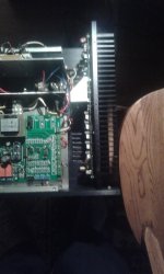
Well , it fits .... (below 1) - 12mm space from amp driver HS to power supply.
Nice 70+ mm ventilation gap over the slewmasters
One tight amp !
Industrial AC "rack" , 80kuf/bridges , val's control board , 1Kva trafo , and
2 full slews in one SMALL case.
The holes were real hard to get perfect with no press - just hand tools.
But I am near perfect (below 2).
The second heatsink and the test of these amps - tomorrow.
Only 2 pair to-3p insulators left - A big kapton or mica spanning all 5 OP's'
would be nice , but I will only test with 1 pair "sacrificial" mt-100's at first.
But , I finally get to hear a "spooky" - ohhhhwww .
OS
Well , it fits .... (below 1) - 12mm space from amp driver HS to power supply.
Nice 70+ mm ventilation gap over the slewmasters
One tight amp !
Industrial AC "rack" , 80kuf/bridges , val's control board , 1Kva trafo , and
2 full slews in one SMALL case.
The holes were real hard to get perfect with no press - just hand tools.
But I am near perfect (below 2).
The second heatsink and the test of these amps - tomorrow.
Only 2 pair to-3p insulators left - A big kapton or mica spanning all 5 OP's'
would be nice , but I will only test with 1 pair "sacrificial" mt-100's at first.
But , I finally get to hear a "spooky" - ohhhhwww
.OS
Attachments
- Home
- Amplifiers
- Solid State
- Slewmaster - CFA vs. VFA "Rumble"