...how DOES one pry open these damn SMPS casings? Do these get sealed by elephants stepping on them?
Are these worth the time & effort modifying, replacing new caps,wires etc or should I forget about SMPS & just stick to my linear psu?
There are several ways to pry them open:
1) Use a heavy screwdriver to separate the two halves of the shell, i.e. progressively crack it open.
2) Same as above, but freeze the adapter in a freezer to make the glue more brittle.
3) Same as 1), but inject a few drops of acetone or gasoline all long the groove to soften the glue.
YMMV, but I find it worthwhile to modify them. The TOPSwitch-based units are probably more reliable than the UC3842B units. The ones with a pi-filter on the secondary will have cleaner DC.
The main changes I've done so far are to the electrolytics and primary-side snubber components - I mostly use Rubycon ZL* on the secondary side. For reliability of the snubber, use a 1kV or higher-rated X7R ceramic (metallized polyester or polypropylene self-healing film is another option, but they tend to be larger than ceramic). I plan to take a look at spread-spectrum clocking eventually.
The Ti link I gave earlier has a complete circuit diagram, with in ruch current control, mute, LED pcb layout with many "finnese" not normally found even in commercial units.
You're excused for not knowing that obscure "OA". opamp is universally known. I too and probably many others, did not know what OA meant.
Yes, AndrewT, indeed, I am too used to calling them by their pet name "op-amps"
Thanks linuxguru, akis too recommends this method. However, I've tried many times without succeeding & at a severe risk of driving the screwdriver through my hand! Stubborn little things! I should perhaps first soften them with little acetone as you've suggested. Clamping in a vice defeats the whole purpose of the exercise!!
However, I've tried many times without succeeding & at a severe risk of driving the screwdriver through my hand! Stubborn little things! I should perhaps first soften them with little acetone as you've suggested. Clamping in a vice defeats the whole purpose of the exercise!!
You need a hard floor to place the unit sideways upon (i.e. one groove at the top where the screwdriver is inserted to pry it open). Use your body weight on the screwdriver to get more force into the groove. The plastic may crack, but no problem - I just use transparent sticky tape (e.g. 3M Scotch tape) to hold the two halves firmly together after re-assembly.
Can someone, or many together, design a SMPS component (with PCB layout of course) that we (the non experts) can then use as a building block for our projects?
One of my requirements would be :
input : 110-240 VAC NOT EARTHED
output : from 5V DC to 40V DC at various amps, depending on the module, 5A would be top requirement, but we could have 0.5A, 1A, 2A and 3A modules.
adj : a pin accepting a voltage that adjusts the DC output of the SMPS
current limit : only to prevent device from destruction (eg shorted output)
thermal limit : to prevent device from destruction
reverse voltage at the output protection : would be nice to have (eg diode at the output)
Once a range of such modules were available, with PCB, we would be able to incorporate them into our designs.
For example I have bought a bunch of LM2596 DC-DC converter modules on ebay, very cheap less than a pound each, and I use them wherever there is a need to convert a usually higher DC to a lower DC. They have a trimmer to adjust the output voltage, easily replaceable with a transistor and a resistor to become variable output.
I have also made a switched capacitor voltage doubler module, so that I can get double voltage where I need.
I can mount those ready made PCBs onto other PCBs in a modular design. So like I said above, if anyone would be willing to design a really good quality SMPS it would be great.
There are already made. Please check here and chose what you need.
Design Examples | Power Integrations
I made some supply using their IC but projected by me and work very well and the schematics can be very simple.
If you subscribe to their site, you can download some very useful tools for helping in calculations.
Or you can search using their tool: http://www.powerint.com/en/design-support/parametric-search#6500
Last edited:
Well, yes and no. Most dual output, isolated SMPSes use dual winding or center tapped transformers. So Vcc can't be regulated independently of Vee. For the small signal circuits of this thread the issue can be avoided if load impedances are high enough the op amps and whatnot pretty much operate in class A with reasonable draw from both rails. Outside of that range the majority of schematics I've seen leave one rail unregulated as it's not sensed. Dual sense isn't necessarily better; with the common case of a half bridge load (typical class AB opamps and power amps or most class D implementations in the DIY power range) if the control loop responds to loading of one rail by increasing the swing on the primary it'll bus pump the other, temporarily unloaded, rail.Switching loops and analogue control signals, keep the switching loops and its related ground return separate from the main ground (connect at on point only) and you're a lot of the way there.
Either way the net result is ground gets servoed, meaning error terms against the audio circuitry's input and output CMRR as well as it's internal CMRR. Hopefully they're small and ultrasonic. But once ground starts moving it's kind of guaranteed the current loops are going to get a bit crazy. Issues of load regulation, load pole motion and DCM entrance aside, it's my experience most of the modules at interesting price points aren't documented well enough to predict how they'll respond in such cases. Some of the ones which are, such as TI's DCP02, are unregulated.
In most of my applications I can't guarantee class A loading or good symmetry between rails. So this poses questions of which dual output modules to acquire and characterize versus, say, stacking two isolated single output modules. I don't have any good answers.
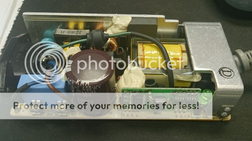
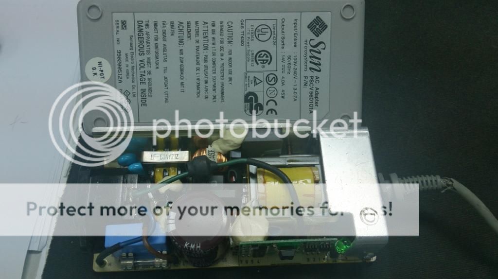
Took apart the SMPS from an old Sun micro LCD monitor, it was built by Samsung over 10 years ago model PSCV 560101A. The built was quite good by looking at it, I will try to use it for powering a TI digital amp. Just that the KMH cap may need to be replaced, any suggestion ? Also can I use 2 of this connected together to form a dual voltage supply +14V and -14V ?


Last edited:
... the KMH cap may need to be replaced, any suggestion ? Also can I use 2 of this connected together to form a dual voltage supply +14V and -14V ?
Yup, the KMH cap is bulging, which is a bit unusual for Nippon Chemicon. However, this one may have been manufactured by licensees like Korea Chemicon or Samyoung, who don't have the same control over materials purity as the parent firm.
This will blow the fuse and short one of the units, if you stack them to get a dual supply - note the earth wire (with ferrite bead) that is connected to the ground of the secondary. That can perhaps be disconnected on one or both of the units without significant downside.
Yup, the KMH cap is bulging, which is a bit unusual for Nippon Chemicon.
Need to be checked. It is posible (usualy this is the case) that only the plastic covers from top to be deformed and the capacitor to be OK. This type of capacitors have (usually) a presure valve on botom side and the top side do not become bulging even if the capacitor is failing.
There are already made. Please check here and chose what you need.
Design Examples | Power Integrations
I made some supply using their IC but projected by me and work very well and the schematics can be very simple.
If you subscribe to their site, you can download some very useful tools for helping in calculations.
Or you can search using their tool: http://www.powerint.com/en/design-support/parametric-search#6500
Thanks for the link, I started looking at it yesterday. Have picked der197.pdf to read on just as an introduction.
Just a quick note to say that lastyear I read a lot on LM2596, bought about two dozens of them, and attempted to make a DC-DC buck converter with it. The schematic is dead simple, component count really low, however it took me dozens of PCB attempts, terrible issues with noise generated on the switching diode and in general with the output collapsing in a heap of noise when the draw was increased to over 2A-3A. I built 4 identical PCBs, using identical components, and each gives me randomly between 3A-3.8A before the noise kills the output. I used a black marker pen and wrote on each PCB module the "rating". But it is so random. Hence I distrust SMPS and I have yet to meet a "clean" one that can deliver the amps it is rated at without seriuous issues.
Syk,..............Just that the KMH cap may need to be replaced, any suggestion ? ................
if you have an isolated High Voltage DC supply you can reform the 400V electro and test the leakage.
Except for the danger of the high voltage, this is a very easy test to carry out.
But do be careful !
You can also measure the capacitance at low voltage.
If you know how, then the esr test is probably the one for telling you it is at end of life.
Would adding a (red & blue) LED each on the +/- DC in a linear psu increase the noise in the audio path noticeably? I've included these in mine to indicate in case the fuses blow!
Syk,
if you have an isolated High Voltage DC supply you can reform the 400V electro and test the leakage.
Except for the danger of the high voltage, this is a very easy test to carry out.
But do be careful !
You can also measure the capacitance at low voltage.
If you know how, then the esr test is probably the one for telling you it is at end of life.
Well, I don't know how to test the ESR, since this power supply had been used for at least 8 years with an average of 16 hours per day I will assume it will be more safe to just replace the cap with a new one.
Thanks
reform the new cap.
The initial current pulse into a discharged electro is enormous. If leakage is also high then the cap can overheat to such an extent that it is permanently damaged. In the extreme it can even explode.
The NTC will slow down the initial charge rate.
You can reform to reduce the leakage rate.
Or start it up very slowly with a Variac.
Well, I don't know how to test the ESR, since this power supply had been used for at least 8 years with an average of 16 hours per day I will assume it will be more safe to just replace the cap with a new one.Thanks
As you may already know, bleeding that cap to ground first before desoldering it may be a good idea?
Here's a fellow who's made very good with Linear's low noise LT3439 switcher:
quietpower:designperformance [teho Labs Docs]
quietpower:designperformance [teho Labs Docs]
Hi,
like the last two links 😉
Used something similar with the LT3471 and Dual-Reg LT3032.
The LT3471 is not galvanically isolated though and the SMD casing not DIY friendly, but it allows for very high switching frequencies.
Also there are two issues which may apply to other similar circuits and devices too.
1: LTs app-notes may not be reliable, eg. Design Note 357 showing a +-15V supply using the LT3471.
The floating feedback certainly is not the way to go and causes issues.
Better design for two separate feedback loops.
The feedback cap values are questionable as they are far off of the calculated values following the calculation formulas provided by LT.
2. The LT3471 seems to be extremely sensitive to stray capacitances.
Just putting a finger for a second somewhere on the feedback components seems to send the part into unstable conditions (detune via feedback loop) resulting in fatal breakdown and a lasting loss of the negative supply output.
3. Similar as in the links provided by jackinnj the switcher stage requires effective post filtering as the voltage regulators used for postprocessing, show good ripple rejection only up to a couple of kHz.
Seems that most LT-Regs are rather poor in this regard.
Regs like TIs TPS7A49xx and TPS7A3xxx better here as they are much ´faster´.
Still, I doubt that high ripple rejection and extreme voltage constancy at lower frequencies is needed anyway, as the regulation of the switcher stages and associated post filtering supplies for enough regulation, not accounted for the circuits own PSRR.
Imho it is more important to supply for high and effective ripple suppression at high frequencies (at and above the switching frequency).
A task where a simple Gyrator stage excels over ´slow´ 3-pin-regs.
Regarding lownoise regs like linked LT1761/1964 in the linked article.
The noise figures apply only for low output voltages and close to no-load conditions!
For +-12V and practical load currents the noise is considerably higher
So, don´t rely on App-notes and Datasheets to be correct or to show the real thing.
Rather assume that many include failures or hide important points.
Don´t expect the companies to correct for failures by revising app-notes, or by putting them off of the websites.
Proove the design by doing Your own calculations.
jauu
Calvin
Last edited:
I just use transparent sticky tape (e.g. 3M Scotch tape) to hold the two halves firmly together after re-assembly.
I've made/glued ABS plastic cases together by dissolving scraps & small bits of ABS in acetone & then using it as a glue to fill cracks & seal these again, then sanding them smooth. Looks good as new!
- Status
- Not open for further replies.
- Home
- Amplifiers
- Power Supplies
- SMPS for small signal analog circuits