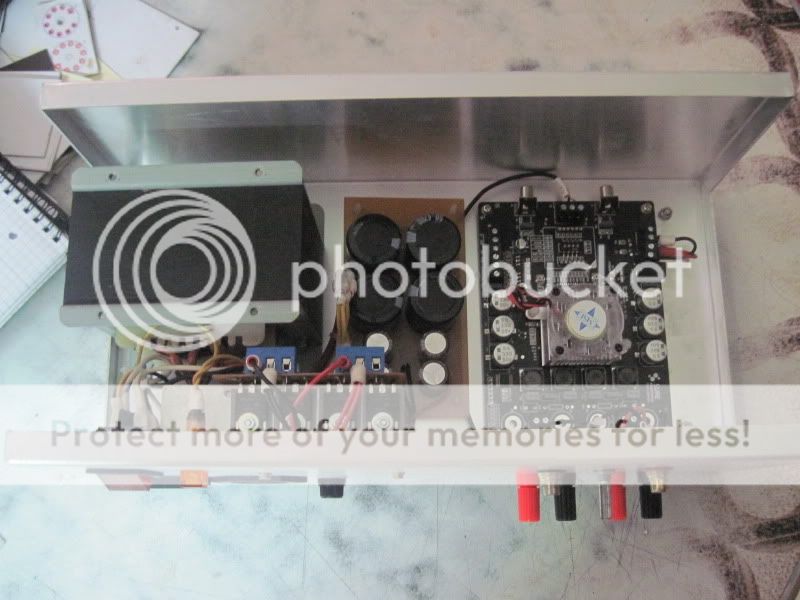
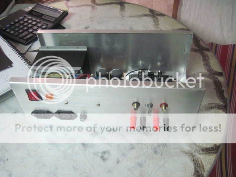
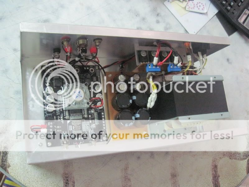
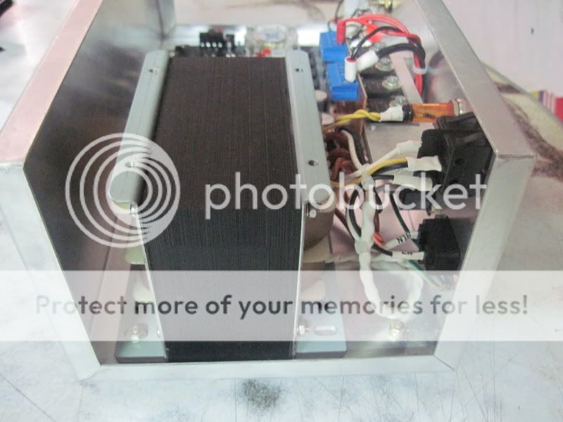
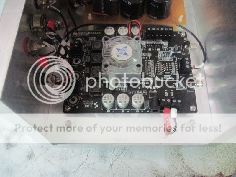
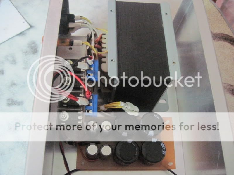
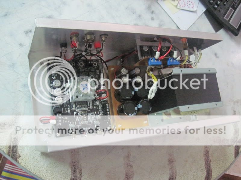
hi, this is my completed assembly:
An externally hosted image should be here but it was not working when we last tested it.
An externally hosted image should be here but it was not working when we last tested it.
An externally hosted image should be here but it was not working when we last tested it.
An externally hosted image should be here but it was not working when we last tested it.
An externally hosted image should be here but it was not working when we last tested it.
An externally hosted image should be here but it was not working when we last tested it.
An externally hosted image should be here but it was not working when we last tested it.
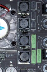
Dr_Vega, OK I'll be carefull if I reroute PS lines! As for the sound, hélas if you have a close look at my board's pic you'll see I've played with gain. And defo no sound in any case :'( BTW, on a singing board it's handy that one can bypass the SMD resistors and try his own favorite resistors via the tulip Vin & Vout! And also do a fine gain adjustement.
Scott, I've read more and yes found that these low value coil don't call for the Zobel.
Simple is better for me, will play with Zobel if I need it later. I guess these caps are MKS/MKT, wonder if some MKP can do and fit!... or things like PPS...
Thanks,
Matthieu
Scott, I've read more and yes found that these low value coil don't call for the Zobel.
Simple is better for me, will play with Zobel if I need it later. I guess these caps are MKS/MKT, wonder if some MKP can do and fit!... or things like PPS...
Thanks,
Matthieu
Also, the manual is for the first version of the amp, so the layout and schematics do not necessarily match your board.
Hi,
they seems to match. Don't mind the V1.0 on the file's name, it's V1 of this new amp, not the older amp wich had a V1.2 manual.
As for the IC you'll read that it's the fan's controller.
Is it now worth to change that set-up for a passive cooling? Avoid a noisy IC by removing R1/R2?
Dreaming on the pdf until I get a working board...
Where did you get the updated manual? Parts Express still has the manual for the first version (AA-AB013). It'd be great to get it and update the instructions for the updates on this thread.
-dr_vega
Hi,
this link work for me:
http://www.sure-electronics.net/download/down.php?name=AA-AB32181_Ver1.0_EN.pdf
I am strugguling (yep even with no working amp...) with tiny and ultra-short legged output film caps (MKS2, MKT/MKC, to fit the original PCB (5mm)) or great MKPs but with added wire lenght and hard to fit? A mid position can be found with top MKT/MKC and inventive lead bending... Those tiny sure film caps (lowest polyester film caps seems) can only be bettered...
Any advice welcome!
Hi,
this link work for me:
http://www.sure-electronics.net/download/down.php?name=AA-AB32181_Ver1.0_EN.pdf
I am strugguling (yep even with no working amp...) with tiny and ultra-short legged output film caps (MKS2, MKT/MKC, to fit the original PCB (5mm)) or great MKPs but with added wire lenght and hard to fit? A mid position can be found with top MKT/MKC and inventive lead bending... Those tiny sure film caps (lowest polyester film caps seems) can only be bettered...
Any advice welcome!
Thanks for the link Malefoda. It worked for me too. I'll send Parts Express a message where to update their manual.
I haven't tried to modify the new board, yet and haven't looked at it closely, I just installed it and am listening to it.
On the older board, those caps had through holes in the board and I mounted big caps under the board. Don't know if the new board is through hole or surface mount.
-dr_vega
Hey All.
Reading this forum is very inspiring and have learned a lot from reading all of your posts; especially @audio1st and @dr_vega with your technical knowhow you have been a service to this community, thank you! I will be sure to reference your posts when I build my amp project using the sure-electronics 2*100 TK2050 boards.
I have some specific questions regarding my particular setup and needs which maybe address here, if needed I am happy to repost these questions in a more proper location, just let me know")
I want to use the sure 2*100 boards in a bi-amp configuration.
I have B&W 602s2 speakers and a Balanced Audio Technology VK-3iX Pre-amplifier.
Question 1:
Would the sure 2*100 amp board match well to my BAT pre amp?
The old rule of thumb goes like this:
The load (amp) input impedance has to be at least 10 times higher than the source (preamp) output impedance to provide a suitably flat frequency response.
Looking at the data sheet for both the sure amp and BAT pre I should be fine
(Sure amp input impedance = 11-22 kΩ | BAT pre output impedance = 1 kΩ)
Are there any other technical requirements that I need to look at when matching a pre amp to an amp? I just want to make sure that I will not be causing any damage matching my BAT Preamp with the Sure amp board, so I am asking here first, instead of taking the wait-and-see approach, plugging in the amp to the pre and causing some potential damage. Some clarification here would be very helpful.
Question 2:
If not the Sure TK2050 board what DIY amp project should I go with, sonically or technically speaking that would match better with my BAT preamp?
Question 3:
This question really shows my lack of understand about amplifiers and setup.
How would I go about physically connecting my pre amp and two individual sure 2*100 boards to power my B&W speakers in a bi-amp configuration- one amp powering one channel. I could go with two PSUs and strictly have 'mono blocks' or I could go with one larger PSU and have a 'dual mono' configuration. If I went the 'dual mono' route, how many DC volts should the (single) PSU be to power my speakers sufficiently?
So this is a two part question:
First part- PSU specks for a 'mono block' and 'dual mono' configuration.
Second part- How would I go about physically connecting my amps to my preamp and my amps to my speakers in the 'mono block' and 'dual mono' configurations. A wiring diagram or signal flow chart could be helpful. I just need to understand how the wiring should go.
Yeah this is a really simple question but I really do not know the answer.
I thank you all for any help you can provide.
For your reference:
sure TK2050 data sheet
BAT VK-3iX Pre-amplifier data sheet
Reading this forum is very inspiring and have learned a lot from reading all of your posts; especially @audio1st and @dr_vega with your technical knowhow you have been a service to this community, thank you! I will be sure to reference your posts when I build my amp project using the sure-electronics 2*100 TK2050 boards.
I have some specific questions regarding my particular setup and needs which maybe address here, if needed I am happy to repost these questions in a more proper location, just let me know
I want to use the sure 2*100 boards in a bi-amp configuration.
I have B&W 602s2 speakers and a Balanced Audio Technology VK-3iX Pre-amplifier.
Question 1:
Would the sure 2*100 amp board match well to my BAT pre amp?
The old rule of thumb goes like this:
The load (amp) input impedance has to be at least 10 times higher than the source (preamp) output impedance to provide a suitably flat frequency response.
Looking at the data sheet for both the sure amp and BAT pre I should be fine
(Sure amp input impedance = 11-22 kΩ | BAT pre output impedance = 1 kΩ)
Are there any other technical requirements that I need to look at when matching a pre amp to an amp? I just want to make sure that I will not be causing any damage matching my BAT Preamp with the Sure amp board, so I am asking here first, instead of taking the wait-and-see approach, plugging in the amp to the pre and causing some potential damage. Some clarification here would be very helpful.
Question 2:
If not the Sure TK2050 board what DIY amp project should I go with, sonically or technically speaking that would match better with my BAT preamp?
Question 3:
This question really shows my lack of understand about amplifiers and setup.
How would I go about physically connecting my pre amp and two individual sure 2*100 boards to power my B&W speakers in a bi-amp configuration- one amp powering one channel. I could go with two PSUs and strictly have 'mono blocks' or I could go with one larger PSU and have a 'dual mono' configuration. If I went the 'dual mono' route, how many DC volts should the (single) PSU be to power my speakers sufficiently?
So this is a two part question:
First part- PSU specks for a 'mono block' and 'dual mono' configuration.
Second part- How would I go about physically connecting my amps to my preamp and my amps to my speakers in the 'mono block' and 'dual mono' configurations. A wiring diagram or signal flow chart could be helpful. I just need to understand how the wiring should go.
Yeah this is a really simple question but I really do not know the answer.
I thank you all for any help you can provide.
For your reference:
sure TK2050 data sheet
BAT VK-3iX Pre-amplifier data sheet
Hi mettalogic, I'm running 2 x of these 2 channel Sure boards in a Bi-amped configuration, so may be this pic helps?
I've changed things a little since then, but I'm running 1 x PSU per board, it makes wiring easier as I've mounted the PSU and amp module on the back of the speaker.
I'm just using a stepped attenuator instead of a pre-amp, but the wiring it pretty simple. Channel 1 = woofer and channel 2 = tweeter.
Just double check everything before you power up, and make sure you don't send any LF to the tweeter otherwise you'll probably kill it!
EDIT: As for signal flow, here is my setup:
digital source ---> deq2496 ---> dcx2496 ---> stepped attenuator ---> Sure board ---> Speakers
What are you planning to use as a crossover?
An externally hosted image should be here but it was not working when we last tested it.
I've changed things a little since then, but I'm running 1 x PSU per board, it makes wiring easier as I've mounted the PSU and amp module on the back of the speaker.
I'm just using a stepped attenuator instead of a pre-amp, but the wiring it pretty simple. Channel 1 = woofer and channel 2 = tweeter.
Just double check everything before you power up, and make sure you don't send any LF to the tweeter otherwise you'll probably kill it!
EDIT: As for signal flow, here is my setup:
digital source ---> deq2496 ---> dcx2496 ---> stepped attenuator ---> Sure board ---> Speakers
What are you planning to use as a crossover?
Last edited:
X-Meridian PC Sound Card to Sure Amps -> Volume too loud
Hey guys,
I'm sorry for the slightly off topic post. Hopefully this isn't totally the wrong place to ask this, so please be gentle if it isn't. I'm planning on cross posted between PC based forum and here to see if I can get an answer.
I'm using an HTPC (running Ubuntu Linux) as my source and have an Auzentech X-Meridian 7.1 sound card which I connect through to the inputs of 4x Sure 2x100W TK2050 Class D amps.
My issue is that the outputs of the Auzentech are known to be "hot" (5Vrms according to the spec sheet) and as a consequence the volume is extremely loud. Right now in order to get the volume to a "normal" listening level I have the volume control in Linux set to 1% (according to the alsamixer approximately -48dB of attenuation, though I'm not sure of the accuracy of that figure), any lower mutes the output.
If I drive the amps from the motherboard sound card, the volume level is perfectly acceptable but as I'm using analog out the sound quality is quite poor. The whole reason for using the X-Meridian is that it's analog quality is supposed to be 2nd to none for it's price bracket.
I've set the gain switches on the Sure amps to the lowest settings, but it is still incredibly loud. I've searched high and low on the internet for means to lower the output voltage of this card and therefore the volume, and though others have complained about it, I've not yet found any viable solutions.
So I was wondering if anyone had any suggestions for how to lower the volume with minimum loss of quality to the sound. I've been considering resistors in the interconnects or stepped attenuators as solutions. I suppose that a passive pre-amp could also perform this task. I am though an audio newbie, so would appreciate any advice people can give.
Oh, whilst I've performed some mods on the sure boards (replaced output, input & power caps, Wuerth Inductors etc) I'd rather not perform any mods on the boards which lowered the output should I introduce a new source.
Thanks in advance,
~Dan
You can build your own in-line attenuators (L-Pad) using 2 resistors per-channel. (Built into the interconnects between the soundcard and the amp's line-in)
Hey,
Thanks for the reply. So having scoured the internet for information I beleive that I'm looking at a ball park -9dB of attenuation (Wikipedia putting the rule of thumb for voltage being -6dB halving the voltage). I'm now trying to plug this into the formulas I've found.
According to the Sure documentation the input impedance of the board is 22K typical (11K min). Of course, since I've modified the input caps and removed resistors I suspect that may well have changed. I also can't find anywhere that gives me the output impedance of the X-Meridian ... so time to go find a potentiometer and my multimeter to measure.
Thanks for your help,
~Dan
Have you read the Tripath datasheet on this? The input impedance is mainly determined by the chosen input gain resistor. Certainly not by the input caps.
The output impedance of your preamp/soundcard should be well under 10 ohms if it is a good one....
Last edited:
Have you read the Tripath datasheet on this? The input impedance is mainly determined by the chosen input gain resistor. Certainly not by the input caps.
The output impedance of your preamp/soundcard should be well under 10 ohms if it is a good one....
Thanks for the pointer v-Bro, it's probably painfully obvious that I'm trying to learn this as I go, so all help is very much appreciated
Is there an easy way to calculate the input impedance by summing the resistors, or is it just easier to try and measure the impedance?
As I haven't got any spare potentiometers lying around though so measuring is going to be a pain. If anyone could point me at a way to calculate these figures approximately (and if that doesn't cause any risk) I'd be quite happy.
Oh, and sorry for taking this thread way off topic
Last edited:
No problem off course, but as I suggested it's all there, page 12 and 13...
http://www.datasheetcatalog.org/datasheet/Tripath/mXyzwqtx.pdf
And with mainly determined by Ri I mean 99%, so that's your input impedance....
http://www.datasheetcatalog.org/datasheet/Tripath/mXyzwqtx.pdf
And with mainly determined by Ri I mean 99%, so that's your input impedance....
ladder or shunt
And this is from another thread
So, i need 4k-10k potentiometer. But as you can see its hard to choose between ladder type pot and shunt type.
I too will use voltage output dac direct to pot.
Can someone advise me wich one to choose?
A 25k attenuator followed by a 25k input impedance is not well suited for a passive pot (nor stepped attenuator).
I would suggest a 10kpot feeding a 50k Zin when used as passive pot.
or 5kpot feeding a 25k Zin. or 20kpot feeding 100k Zin.
The 5kpot will drive reasonable lengths of interconnect.
As the pot value increases, the permissible capacitance (from cables and RF filter) reduces drastically. A 25kpot may require direct connection to the Power Amp input filters.
And this is from another thread
also, 10k is a bit low in impedance for a shunt volume Try to up in the 20k-100Kohm area, for best results. Otherwise, there will be such a change in the loading, that the result will be uneven sonics throughout the volume range.
Yes, I run a Behringer DEQ or DCX2496 direct from the dac, out through a coupling cap as does DrVega. Panomaniac prefers transformers but it gets expensive with 6 in a DCX. My attenuators are fixed series 4k with a switched shunt. This allows an attenuator to be built with only 1 switch deck. A series attenuator uses 1 deck but has 12-24 solder joints and resistors in the path compared to only 2 for ladder or shunt . Ladder types seem to have technical advantages until you think it through. A 10k ladder is an easier load for the source at quieter levels although I have been reading that measured performance of the dac chip can actually improve when loaded with 3k. The sonic challenge for a passive volume control is the high output impedance which is, in effect a restriction in current that would be useful to drive the signal through the R, C, and L of the following cables and input stages of the amp. E.E. type theorists that don't believe in listening insist that these values are so low in any reasonable cable length so as to be ignored, but thousands of reports of listening tests by people drawn to the cheap price and purity of passives show mixed results when replacing an active volume control due to the increased interactions with a passive. The two keys to getting superior sonics along with the cheaper costs of passive are in choosing the lowest possible output impedance that your source will still drive, and minimizing the the cable length that follows the attenuator. Now, back to ladder vs. shunt. A 10k ladder (or series, or pot) has 10k input at all settings but the output impedance will change from 0 at full volume to 6.6k at -12db to 8k at -18db and continue to rise at quieter levels. The shunt style has a 4k output at all levels and the input is 20k at -2db dropping through 4.6k by -18db. But the 4k actually has a lower output impedance than the 10k series (pot) or ladder from -5db and quieter where most controls end up getting used, staying at 4k while the others are rising.
.
2 feet cables seem short but in my experience, you will still hear them robbing you slightly. If aesthetics and convenience are secondary to getting the best sonics, I would recommend mounting the volume controls to the boards in the empty spot between the connectors and the heat sink. Or at least hardwiring from a housing front panel to the amp to keep the wires to 6 inches.
.
So, i need 4k-10k potentiometer. But as you can see its hard to choose between ladder type pot and shunt type.
I too will use voltage output dac direct to pot.
Can someone advise me wich one to choose?
Passive Attenuator
I can run my AK4395 and CS43122 dacs with transformer or cap coupled direct out and change back and forth just by moving the interconnects. This has allowed me to discover that with both legs of the dac contributing through the trannies in a balanced to single ended conversion, they have enough power to drive my 4k direct attenuators much better. One leg out through the caps sounds slightly closed in by comparison into the 4k load the attenuators provide at quieter settings. At louder settings, say -2db, the attenuators input impedance is 20.4k. At this load the beauty of the caps can sound better and are much cheaper than the transformers. The AKM chip happens to have the perfect level to connect straight to the Sure 2X100 with no volume control. This arrangement reveals that the Dayton foil caps do sound better than the best transformers but only if the load is eased to 10-20k at which point, digital volume control in the range of 0 to -12db sounds better than having any value of added series resistance of any style of analog volume control which would favor the availability of a straight through setting with a ladder. Which is not to say that you can use a control with 20k in series with the signal in order to ease the load. I also have 20k series/ switched shunt direct attenuators. I changed the input terminating resistors and gain setting resistors R14,34,11,32,30,16 in an amp to 150k in order to compare 4k versus 20k attenuators and still maintain a suitable 7:1 ratio. I found that the 4k series resistor allowed more of the fine detail through. These are direct attenuators that plug right onto the amp's input connectors. The difference would be much greater if there were any length of interconnect involved, favoring the 4k value further. So where does this leave us? Since the direct out dacs are much cheaper to run with one leg through caps and have a lowish level that needs to be run nearly wide open through a terminating load no lower than 10k, I have decided start work on a new ladder type attenuator. Ladders cost twice as much per step but do have a sonic advantage over shunt types, of reduced series (output) impedance in the wide open ranges from 0 to -12db that I now need. I have never tried the current crop of series attenuators which can duplicate a ladder with one deck, due to the massive number of solder joints they introduce into the circuit but I guess I should also explore these as I have learned over the years, and more so with everything new I experiment with, you never know what something will sound like based on theory, until you listen to it. It is possible they could sound ok at wide open settings which would place most of the solder on the ground side. So I need to find out what the minimum value that sounds good with the direct out AKM is ( the CS chips have slightly more level and power so should be less fussy) and pick between ladder and series. Whatever I build next will use the excellent and affordable Susumu surface mount resistors as they sound better than any through hole resistors in this critical application.
So, i need 4k-10k potentiometer. But as you can see its hard to choose between ladder type pot and shunt type.
I too will use voltage output dac direct to pot.
Can someone advise me wich one to choose?
I can run my AK4395 and CS43122 dacs with transformer or cap coupled direct out and change back and forth just by moving the interconnects. This has allowed me to discover that with both legs of the dac contributing through the trannies in a balanced to single ended conversion, they have enough power to drive my 4k direct attenuators much better. One leg out through the caps sounds slightly closed in by comparison into the 4k load the attenuators provide at quieter settings. At louder settings, say -2db, the attenuators input impedance is 20.4k. At this load the beauty of the caps can sound better and are much cheaper than the transformers. The AKM chip happens to have the perfect level to connect straight to the Sure 2X100 with no volume control. This arrangement reveals that the Dayton foil caps do sound better than the best transformers but only if the load is eased to 10-20k at which point, digital volume control in the range of 0 to -12db sounds better than having any value of added series resistance of any style of analog volume control which would favor the availability of a straight through setting with a ladder. Which is not to say that you can use a control with 20k in series with the signal in order to ease the load. I also have 20k series/ switched shunt direct attenuators. I changed the input terminating resistors and gain setting resistors R14,34,11,32,30,16 in an amp to 150k in order to compare 4k versus 20k attenuators and still maintain a suitable 7:1 ratio. I found that the 4k series resistor allowed more of the fine detail through. These are direct attenuators that plug right onto the amp's input connectors. The difference would be much greater if there were any length of interconnect involved, favoring the 4k value further. So where does this leave us? Since the direct out dacs are much cheaper to run with one leg through caps and have a lowish level that needs to be run nearly wide open through a terminating load no lower than 10k, I have decided start work on a new ladder type attenuator. Ladders cost twice as much per step but do have a sonic advantage over shunt types, of reduced series (output) impedance in the wide open ranges from 0 to -12db that I now need. I have never tried the current crop of series attenuators which can duplicate a ladder with one deck, due to the massive number of solder joints they introduce into the circuit but I guess I should also explore these as I have learned over the years, and more so with everything new I experiment with, you never know what something will sound like based on theory, until you listen to it. It is possible they could sound ok at wide open settings which would place most of the solder on the ground side. So I need to find out what the minimum value that sounds good with the direct out AKM is ( the CS chips have slightly more level and power so should be less fussy) and pick between ladder and series. Whatever I build next will use the excellent and affordable Susumu surface mount resistors as they sound better than any through hole resistors in this critical application.
Ladder vs shunt
Single ended ladder attenuators costs twice as much per step than shunt due to needing 2 switch decks versus 1 which adds up when considering 6-8 channels in an active cross system. The difference in input and output impedence is only signifcantly better for the ladder from 0 to -12db or so. Any levels quieter than this, which is where most controls end up being used at -20 to -30db, and the impedances are nearly the same for any given step so the shunt can sound just as good at half the price. The price/ performance of the shunt style really shines when using a balanced signal where the shunt attenuator can still be realized with 1 deck while the balanced ladder attenuator needs 3 to 4. It is only now, with the lowish gain Tripath amps and direct out dacs, that I have the need for the 0 to -12db range which favors the ladder or series attenuator.Shunt type has no constant impedance, ladder is ALWAYS better.
Last edited:
Who says my system isn't always at 0 to -12db attenuation??
No you're right, but if I want simplicity and low cost a 12 step series attenuator with good well matched resistors is fine too. That's already a zillion times better than the best potentiometer....
No you're right, but if I want simplicity and low cost a 12 step series attenuator with good well matched resistors is fine too. That's already a zillion times better than the best potentiometer....
Last edited:
- Status
- This old topic is closed. If you want to reopen this topic, contact a moderator using the "Report Post" button.
- Home
- Amplifiers
- Class D
- Sure Electronics New Tripath Board tc2000+tp2050