Member
Joined 2009
Paid Member
That 1k resistor is the LTP collector load and therefore sets the voltage gain. Reducing it will reduce the OLG and this shifts the design away from the original. The dc-offset will always be trimmed out to zero using the potentiometer which avoids fiddling around with transistors until you get something you can rationalize as being acceptable. The real question for me is whether balancing the LTP is even desirable and did Naim really match transistors in production ??????One thing that jumps out of the page which I had forgotten is the VAS is a constant voltage clamp ( that sets an almost constant current ). 1K sets this with Vbe. The time it shows an important difference is if the ZTX753 is being starved and starts to switch off. Vbe is very low as many say for ZTX753. If we have the tail current one side or the other ( high or low ) we could see the fake single transistor distortion curve. Or if we like the least second harmonic curve we dial a 50/50 balance. Thus we need to make 1K smaller if a quest to get something " better ". As with my musing 1.23 mA here. It probably is a better result although not pushing the VAS any harder. I wonder if 810R and 22K would be better? When brave perhaps 510R 11K and CCS Re 330R. DC offset should be 5 mV. I feel 39pF VAS cap will still be OK. It's 69pF total.
I know this isn't what you were aiming at but it amused me to think about current 'waste' in the LTP as it isn't the first concern for either of us in a power amplifier that'll be lucky to see 50% efficiency in normal use! (the speaker protection circuit uses 5mA).Quite interesting two points exist for the 2nd harmonic balance. One of them wastes current.
Ultimately, the footprint on the pcb limits my choices. I wanted to use high quality electrolytics and I like Nichicon MUSE for this. I don't think it would be easy to find a 10mF cap for that spot. I haven't finalized the off-board capacitance - my sense is to use nothing more than diode snubbers but I could reduce the charging current pulses along the wires to the pcb if I include some additional capacitance right at the rectifier and then keeping the rectifier and this additional capacitance physically close with the trafo to minimize current loop radiation.I rather like your 0R22 + 4700 uF. In fact you could make it 10 000 uF ...
Member
Joined 2009
Paid Member
Design Error !
Well I've sifted through the evidence and it has lead me to a design error on my part.
The square wave test depending on signal ground...
The unlikely mis-balance in LTP current...
In my enthusiasm to include a 10R ground-lift resistor (R2) into the Naim design I had left the current source bias resistor (R4 in my schematic) terminating into signal ground instead of power ground. Oooops. This causes 1.7mA to flow through the ground lift resistor which develops 17mV of bias offset that requires a lot of mis-balance from the LTP to address.
I'll be fixing this with my soldering iron to see if it helps.
I also measured some more currents and voltages and conclude that the Hfe of the LTP transistors are 550 and 595.
Member
Joined 2009
Paid Member
Fixed It !
The error was fixed. Now the LTP is more balanced, input leg at 533uA through R5 and feedback leg at 499uA through R6. The difference is 34uA and most of that will be the base current for the VAS device. I was able to easily set the dc-offset to less than 1mV; of course it drifts around a little but keeping it to a few mV is a breeze.
I re-measured base current to the input devices at 85uA to 90uA which implies an Hfe of 587 and 590 for the two devices. Of course my measurement error is at least 1%.
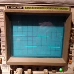
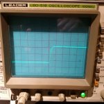
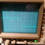
I re-measured the square wave into 7R5 load. Still nice and clean with rounded corners.
To test the speaker disconnect I turned off the +ve rail power supply only, and watched the dc-offset at the output climb slowly as the capacitors discharged. The green LED cut off the output at well under a volt. Same result when turning off the -Ve rail first.
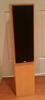
I also wheeled out one of my B&W floor standers that are normally used for my HT surround speakers. The sound was refined and punchy. And that's it for tonight.
The error was fixed. Now the LTP is more balanced, input leg at 533uA through R5 and feedback leg at 499uA through R6. The difference is 34uA and most of that will be the base current for the VAS device. I was able to easily set the dc-offset to less than 1mV; of course it drifts around a little but keeping it to a few mV is a breeze.
I re-measured base current to the input devices at 85uA to 90uA which implies an Hfe of 587 and 590 for the two devices. Of course my measurement error is at least 1%.
I re-measured the square wave into 7R5 load. Still nice and clean with rounded corners.
To test the speaker disconnect I turned off the +ve rail power supply only, and watched the dc-offset at the output climb slowly as the capacitors discharged. The green LED cut off the output at well under a volt. Same result when turning off the -Ve rail first.
I also wheeled out one of my B&W floor standers that are normally used for my HT surround speakers. The sound was refined and punchy. And that's it for tonight.
Attachments
Last edited:
The wasted current was tongue in check. It might give slightly more DC off set.
I still think 810R worth a try instead of 1K. Input impedance could be as low as 270R for the ZTX753@10mA. I suspect 100R ( 68R ) VAS CCS Re would be worth a try. As this reduces transconductance we could then back off the 39pF ( wasted transconductance if you think about it ). Did anyone calculate the gain of this VAS? One interesting result of reducing the transconductance is to make the VAS more linear. We might have better HF doing this mild change, a free lunch. Z in could shift from 270R to 400R. If the ZTX753 was selected for a gain of 200@7mA we might see 800R. I suspect Cdom to be 22pF at this point. The HF improves two ways. Less > 10 kHz distortion and less TID. I suspect it also deals with back EMF better. The Naim 0R22 instead of choke helps back EMF recovery. Mostly what gets past the biasing needs.
The output protection might add a bit of HF distortion. I measured that idea and have to say it works.
Some say 100 mV DC offset will make for a better sound. Even 250 mV 8R is 1 watt which should be OK. We can do three things with this.
Pull the speaker back for least 2nd harmonic and slightly higher SPL( 2 dB ? ).
Push it forward for more 2nd. 2nd sounds louder so this might be a winner. This is due to coil/magnet positioning. The output looks exactly like a triode valve.
DC off set might give crossover distortion a kick ( 0V might be a bad result ). This one might not be a real advanatge, but has been debated. Hiss also can make crossover distortion melt away. I make no strong claims for this. It's just to say what seems worse might be a friend. I thank Michael Creek for the hiss idea. He found out by accident. His first 4040 had zero bias by mistake yet it sounded OK. The hiss saved the day. It was about - 80dB. When he rebiased the transistors gave problems as they could latch up. Sadly doing the right thing gave him problems. It some ways the Darlingtons were too good.
and adds a 17mV error into the base voltage measurements............... This causes 1.7mA to flow through the ground lift resistor which develops 17mV of bias offset that requires a lot of mis-balance from the LTP to address.
That makes them c grade not bc546a...................I also measured some more currents and voltages and conclude that the Hfe of the LTP transistors are 550 and 595.
But bc546c are quite difficult to source. Are they bc550c?
http://www.farnell.com/datasheets/609435.pdf?_ga=1.183141670.108595882.1487667949
I was looking without sucess for a VAS transistor when I noticed the capacitance of 530pF base emitter in the PDF. That must be part of the picture? I guess ZTX753 is similar? Any thoughts? Also, although small how would 10R external VAS Re sit with that? I guess too small to matter.
I was looking without sucess for a VAS transistor when I noticed the capacitance of 530pF base emitter in the PDF. That must be part of the picture? I guess ZTX753 is similar? Any thoughts? Also, although small how would 10R external VAS Re sit with that? I guess too small to matter.
I started using 10R emitter degen some years back and the thinking was that if the variable emitter impedance set by 26/mA moved up and down with slight changes in collector current, by increasing the Re to three times the average impedance alone we could linearize the voltage swing at the bias generator.
So, assuming emitter impedance was around 3ohms, by adding 10R of degen the Re of 13would proportionally reduce. Of course loop gain dropped, but then, the linearity increased, a reasonably compromise.
I then found that in critical listening tests it sounded subjectively superior, although the THD slightly increased.
HD
Member
Joined 2009
Paid Member
The digikey receipt shows BC546C. I don't think I noticed that when I ordered them.But bc546c are quite difficult to source. Are they bc550c?
Member
Joined 2009
Paid Member
One interesting result of reducing the transconductance is to make the VAS more linear.
It's all tradeoffs in the end and listening tests with lots of tweaks could be fun. However, the goal here is to follow in JVs footsteps a little.
Self proposed that VAS linearity was more or less guaranteed because of the local feedback provided around the transistor by Cdom.
I knew JV. It's not him you are following really. I always suspected it was Alan Mornington West although he is too modest to say so ( I have an email I can't quote ). Julian made a tape recorder called Chiltern if I am right. He said recordings he made never translated to how he remembered the venue. The tweaking started there. Alan perhaps realised the Quad 303 had the magical qualities Julian wanted and served up the right circuit. In addition Julian wanted punch which the Quad wouldn't do as well as the Naim. It is said the NAP160 was Alan's design to replace Quad 303 which was displaced by the 405. I have no idea if true.
Julian in some ways was not someone you would want to meet. Very forceful and always ahead of the thinking speed of most people. I often wondered if he had been trained to give that illussion.
Lets analyse Re+re of the VAS. If Self is correct it will not make the VAS more linear as an I to V converter doesn't work that way. Perhaps he is right.
There is a nugget of pure gold here. We should find a point where Re forces Cdom=0pF.
Re+re should cause the I to V ( TIS ) to become a truer VAS.
Take seriously the idea of the CCS current.
Marty Feldman in The Last Remark of Beau Geste has an identical twin brother who is more identical than him in his words ( Michael York I think was the other ). That's what this amp is really. A less identical brother of a different mother. I would take that as an excuss to make it exactly how you like it. Buy a Nait 3 to keep you on target. It can go on eBay when you have what you truely like. JV isn't someone to overly follow. Non here would deplor that I am sure?
Member
Joined 2009
Paid Member
Fair enough. But we have a design and a pcb - the question now is whether further changes are warranted. I will need to do some listening tests of course, to identify the benefit of further changes because technically the thing works as-is. Significant changes now makes it a different design, a new project. Small changes designed purely for listening purposes have to be validated through listening. Measurements can only confirm that any subjective changes caused no unintended harm to stability etc.
For this, I would need to build a second channel. I can built it with some differences, or some adjustability and then compare it with the first channel.
But how will I know what to listen for - buying a Naim to make direct comparisons is a bit on the keen side. I also find speaker choice and source choice is important. So in the end, I feel 'safer' keeping close to the original, although not fanatically so.
Last edited:
That explains the very low input offset voltage.The digikey receipt shows BC546C. I don't think I noticed that when I ordered them.
The base current using the c grade is very much lower, than if an a grade had been used.
Please make a YouTube video so we can all judge the sound quality.I will need to do some listening tests of course, to identify the benefit of further changes because technically the thing works as-is.

That's like watching Come Dine With Me. We can only guess how the food tastes. However the people matter most. If you don't know the show you should.
On the changes, just try a VAS resistor perhaps and add a resistor to 1K to make it 810R ( 4K3 ). Time has changed much due to transistors upstream of the VAS. Tasting notes with these tests should please.
Put in some solder posts in for Cdom? When I tried VAS emitter resistor I used a 1/8 watt type sweated onto the emitter lead. 10R seems about right.
Last edited:
Fair enough. But we have a design and a pcb - the question now is whether further changes are warranted. I will need to do some listening tests of course, to identify the benefit of further changes because technically the thing works as-is. Significant changes now makes it a different design, a new project. Small changes designed purely for listening purposes have to be validated through listening. Measurements can only confirm that any subjective changes caused no unintended harm to stability etc.
For this, I would need to build a second channel. I can built it with some differences, or some adjustability and then compare it with the first channel.
But how will I know what to listen for - buying a Naim to make direct comparisons is a bit on the keen side. I also find speaker choice and source choice is important. So in the end, I feel 'safer' keeping close to the original, although not fanatically so.
Are you near to Oxford? Wasn't sure from the Herefordshire bit. These days I have no Naim ( except an AV1 ). If I did I would have gladly loaned one.
Member
Joined 2009
Paid Member
I was born in Oxford and grew up in the area (Didcot, Abingdon, Drayton, Hanney), returned there for awhile to do a phd. I now live in Canada. But my parents are close to Ross-on-Wye and I visit them at least once a year and sometimes find myself in Oxford. I was there last summer, enjoyed some time at the Turf Tavern.
Member
Joined 2009
Paid Member
I don't think I want to do too much tweaking, but for the 2nd channel the suggestions are piling up. For better sound, here are a few suggestions that I can remember:
a) no RC isolation of the front-end (wire link instead of R + diode)
b) VAS emitter degeneration (10R butted up to emitter lead), which will reduce OLG
c) tweaks to the driver base 'phase correction' network resistor values
d) output inductor (can try it first off-board)
e) use a NAC pre-amp (next project perhaps!)
f) more capacitance at the rectifiers to increase total filtering
g) ?
- Status
- This old topic is closed. If you want to reopen this topic, contact a moderator using the "Report Post" button.
- Home
- Amplifiers
- Solid State
- TGM10 - based on NAIM by Julian Vereker