Member
Joined 2009
Paid Member
Hi Nikolai,
Well I have found my interest in Naim pre-amps growing during the duration of this project and the discussions on this thread. I did see some interesting information about their pre-amps and the NA729 filter for example. I don't know if I should send this thread off on that topic or save it for another thread with proper focus, but you might like to know that I do have in front of me right now a print out of the schematic for the NA729 and the NA321 boards (rather like the design you attached above). I have also been thinking about making a modular pre-amp so that I can have something working more quickly and add / change boards in the future. My inspiration was not from Naim in this case, but from DNM (another user of DIN connectors by the way).
I will say again that I'm not decided about my opinion on the treble yet, I do need to do more listening of this amp.
Last edited:
And, I even imagine why there is not a clear idea of the correctness of high frequencies .... A fairly accurate implementation of the power amplifier - has a high potential of its own. And, with some of the records correctly and accurately recorded - there are no such audible problems. Of course, this depends, in part, on the signal source. But on such recordings you can suddenly stumble when it starts to feel: lack of sound balance.For example, for me it's a collection of the ABBA group, a CD-disk of the studio POLYDOR. The arrangement itself, the features of the voices and the sound engineer's work - apparently, this provoked. And, with such problematic records - the complete system of NAIM cope most delicately. It's like automatic adjustment of "brightness" and "contrast", when the overall illumination changes.I will say again that I'm not decided about my opinion on the treble yet, I do need to do more listening of this amp.
Also, in my opinion, it's better when there is no volume control at the LPT input itself. And, the adjustment of the signal level itself takes place at the input of the preamplifier. If you have an electronic level control at the source, then this may not apply to your case.
Having a relatively simple, discrete preamp lying around after you finish with the project won't hurt anyway. I copied the basic line level electronics of a NAC32 many (uhh...35  years ago) and squeezed them into a miniature "chrome bumper" style case made from a scrap of RHS alloy, about 100 x 40 x 130 mm. Well, it looked convincing to me and lasted all that time, built on FR4 with a hand drawn pattern, standard 1% MF resistors, BC 5XX series transistors and Elna caps, though I began with Tantalums.
I found it very useful as a compact, portable control device that could be stored and used anywhere. Having a single regulated supply rail, it could also be powered from almost any + rail or bench supply. It would be a shame not to fit the DIN connector and make up a SNAIC type lead but I'm sure you can live without one yet still have "the sound" if cables and grounding follow much the same paths.
If you are at a hiatus with the amplifier until checking what a NAC preamp can do for the sound, then it would seem logical to start a new thread with a bold headline and link here - as you would in any new thread split off from another, lest folk get confused and reply randomly in both threads, which confuses everyone else We can still reply in the amplifier thread, if that's our interest.
years ago) and squeezed them into a miniature "chrome bumper" style case made from a scrap of RHS alloy, about 100 x 40 x 130 mm. Well, it looked convincing to me and lasted all that time, built on FR4 with a hand drawn pattern, standard 1% MF resistors, BC 5XX series transistors and Elna caps, though I began with Tantalums. I found it very useful as a compact, portable control device that could be stored and used anywhere. Having a single regulated supply rail, it could also be powered from almost any + rail or bench supply. It would be a shame not to fit the DIN connector and make up a SNAIC type lead but I'm sure you can live without one yet still have "the sound" if cables and grounding follow much the same paths.
If you are at a hiatus with the amplifier until checking what a NAC preamp can do for the sound, then it would seem logical to start a new thread with a bold headline and link here - as you would in any new thread split off from another, lest folk get confused and reply randomly in both threads, which confuses everyone else
We can still reply in the amplifier thread, if that's our interest. 
Here is the Mission Cyrus that sold in the 1000's. Lucky for them they didn't read about the blameless amplifier. To my ears the Nait 2 was a better design. My eyes say it should have been mostly the Mission that should win. The big deal was the Cyrus sounded great at normal listening levels. Below or above that it was bland or unhappy. As luck would have it this could be tuned out by fine setting the volume ( many are like this ). My eyes tell me that the power supply was the reason. One has to remember if an amplifier has this trait it will be found by the music. The Rotel RA931 for all it's faults didn't do this. In some ways the Naim and the Cyrus could learn from the Rotel's dating back to RA820.
The Cyrus is an interesting mix. It looks like a nasty op amp ( LM324N ) input except Cfbp. The VAS is a bit like op amps. Note Q21 as very different. C35 says something is fussy, or is it just the best idea? Output is Quad/Crimson style, said to be hard work to get stable ( could be the fizzy sound I sometimes heard ), worth perfecting as said to not be too critical on bias ( 7 mA ? ). I would prefer the JLH bipoar in, inverse FET out for that. C47/49, yikes!
Q23/25 current mirror gives a very healthy output. The gain of the ouput stage is so high I doubt reducing it to 1/3 would stop the good things happening. If so the Cfbp LTP would be a bit less busy. This amplifier was treated by the technical people of the day as designed by a genius. I think they were taken in. All the same it might have something.
Ian. Using the 5 pin DIN is ideal for the preamp connections. The least thought of reason is if pulled out by mistake when working often nothing bad happens ( locking ring stops it if using the posh ones ). XLR loved for the same reason. Neutrik Profi RCA are expensive and to my ears less good than the cheap Rean ( normal style RCA ) versions of the same brand. Pro Audio where forced has to use that version to mimic the XLR, it saves blow ups. Sending a signal through a spring isn't good when the Profi RCA. If anyone is interested, I find tubular RCA's the best. They cost less also. Deltron were the make Naim suggested. Deltron tubular Banana plugs were Naim prefered types. They have the hard steel wire spring and cost less than £1. 90% as good as the Naim banana plugs. 100% if he wire is formed around the screw thread and finished with heatshrink if NACA5. For some speakers that was the better option. For cost also.
Naim thought DIN far better than RCA ( me too ). BNC also, they used 75 ohm type. RCA was only used because it was dirt cheap, Japan liked that. Alas it is now the standard. Lucky it's " only " audio as the cable seldom matches the RCA at RF. Some say 300 ohm cable works best with RCA, sometimes no screen is OK. Could be 230 ohm screened is what RCA needs.
You know we got further on this thread than this poor guy. It's a really good point being made. Why no " feedback "?
http://www.diyaudio.com/forums/solid-state/109983-unusual-vas-cdom-variation-ideas-web-page.html
http://www.diyaudio.com/forums/solid-state/109983-unusual-vas-cdom-variation-ideas-web-page.html
The way I see this one is: We know that the phase difference between input and output will not be zero across the entire frequency range so the instantaneous voltage at the output might be zero when the input is not zero, but the feedback loop is 'always on', the error amplifier is always comparing input and output - zero is just one voltage of an infinite number of possible voltages, there is nothing at all special about this voltage as far as the error amplifier is concerned which of itself doesn't 'know' where the ground reference is. However, the feedback loop can't fully correct the distortion at the output. If the distortion is worse around cross-over it isn't because the error amplifier went to sleep, it's because there is more distortion at cross-over. I don't see an escape from that in this project since it isn't designed to operate in Class A, or with sliding-bias and there is no provision to increase the feedback factor by adding more OLG.
Still, as there are many examples of quasi-comp amplifiers around which people like, the cross-over distortion of this type of output stage is not an obstacle to enjoying the sound. Unless it's biassed wrong perhaps.
The VAS is a solid design, used in good sounding amplifiers. The LTP is a solid design too, it's just that '22k' resistor that presents something new here. All the elements by themselves are 'proven' somewhere it seems. My spider sense therefore, is that the key element remains the compensation, along with the interaction between amplifier and load.
I have built several versions of the Naim circuit and they all sound very different:
Ebay NAP140 "clones" with dual mono supply using toroids = harsh, aggresive, overtly "PRATy".
NCC200 (twice, 'cos there's so much fuss about them on PFM) = pretty good but not the Naim sound.
NAP200 Ebay clone with EI transformers (good with toroids but gets a bit harsh at higher levels) = the best SS I have built, out of many 10s of amps.
I don't think you will solve your harshness problem with a Naim preamp - actually you will probably end up forever mucking around with PSs for the pre, because the Naim circuit is exceptionally dependent on this. If your amp is harsh... it's the implementation.. Newer Naim power amps are not harsh sounding!
If you are concerned about the 22K, just short it out and have a listen. It makes almost no difference to the dc or ac conditions, but it does change the sound significantly. Nigel has told you how (his PM250 comment) it affects the sound.
Thanks Dave, very sage advice.
Hope someone reads the Cdom replaced with choke link. I thought of it before, no idea if the Naim design could take it. It never occured to me removing Cdom removes a very bad feedback route. One should use something like 2SB716 to get the very best of that idea. Not the gain, Cob. I bought some 2SB716. Well, I thought I did. I suspect they are 2N5401. Looking again 2N5401 is not a bad device. Cob 6 pF max and OK on dissipation. Select for highest gain. Then I find it is obsolete!
KSA992FTA FAIRCHILD SEMICONDUCTOR, Bipolar (BJT) Single Transistor, PNP, -120 V, 100 MHz, 500 mW, -50 mA, 300 hFE | Farnell element14
With a bit of work this transistor could work. Make the collector PCB area large to get 1 watt and fit a TO92 heat clip. The Cob and Ft are supurb. And gain is incredible. Much like the old 2SA970 or 2SA872. Make the current 8mA and it's very OK. 320 mW if so. The price is good. One for the treasure box.
Member
Joined 2009
Paid Member
The 2nd channel powered up this morning, first time perfect. Thermal stability is very good, dc-offset can be trimmed to < 1mV.
I decided to try putting some capacitors in parallel with my 7R5 load resistor and look for evidence of degradation in the square wave performance. I started with 2.2nF, then 22nF and finally 220nF. I figure this gives me something that covers the range of normal to capacitive speaker cables. I could find no evidence of any issues, no changes in the square wave response, no evidence of parasitic oscillations, no errant behaviour in current draw etc. I take all this as a good sign.
I decided to try putting some capacitors in parallel with my 7R5 load resistor and look for evidence of degradation in the square wave performance. I started with 2.2nF, then 22nF and finally 220nF. I figure this gives me something that covers the range of normal to capacitive speaker cables. I could find no evidence of any issues, no changes in the square wave response, no evidence of parasitic oscillations, no errant behaviour in current draw etc. I take all this as a good sign.
Member
Joined 2009
Paid Member
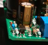
Thermal compensation
The Naim Vbe multiplier as shown in the clone schematics over-compensates the output stage thermal behaviour. By loosely coupling it, either having it dangling inside a closed box or touching part of the box, you can 'adjust' the thermal compensation sensitivity.
But the CCS is also sensitive to temperature. In a closed box the two diodes and the CCS transistor should sit inside the same ambient. But you get a more defined behaviour when you put them in physical contact with some thermal grease between them. It also provides ancillary coolling for the CCS transistor through the diodes, their leads and associated pcb trace area.
In the attached image you see how I've mounted the CCS transistor. It's bent over 90 degrees so that it can lie flat on top of the two CCS diodes.
Attachments
I have built several versions of the Naim circuit and they all sound very different:
Ebay NAP140 "clones" with dual mono supply using toroids = harsh, aggresive, overtly "PRATy".
NCC200 (twice, 'cos there's so much fuss about them on PFM) = pretty good but not the Naim sound.
NAP200 Ebay clone with EI transformers (good with toroids but gets a bit harsh at higher levels) = the best SS I have built, out of many 10s of amps.
I think you have good ears.
If your amp is harsh... it's the implementation.. Newer Naim power amps are not harsh sounding!
The harshness is a collaboration between the amp and the power supply. The source is the power supply but it is the amp that "amplify" it. Thats why Naim use complex power supply. This is to fix the only weakest point in the circuit.
If you are concerned about the 22K, just short it out and have a listen. It makes almost no difference to the dc or ac conditions
No, you may send the amp into oscillation. It has big effect on AC. Lowering it I think will reduce the phase margin.
No, you may send the amp into oscillation. It has big effect on AC. Lowering it I think will reduce the phase margin.
Minimal change to loop response on the 2 different amps I tried this on (note: real life, not simulated). And actually the phase margin is marginally worse with the 22K in play.
All the Naim type ciruits I have built are/were unconditionally stable and generally very well behaved. I did manage to find some delay on the bottom half of the o/p stage turning on, but this was under test conditions which were totally unrepreseantive of real world use.
dc-offset can be trimmed to < 1mV.
How did you do it? I found it difficult to lower the positive dc without changing the equilibrium i already have.
And actually the phase margin is marginally worse with 22k
It shows that 22k was a "blind" copy of the Naim circuit. My Naim clone is using zero resistor there. Bigun's cct is i think optimally used 22k.
Member
Joined 2009
Paid Member
How did you do it? I found it difficult to lower the positive dc without changing the equilibrium i already have.
Remember, I have a potentiometer to vary the CCS to the LTP which is a somewhat traditional method of fine tuning. Of course, I begin with a fairly well balanced LTP but it's quite a nuisance with fixed parts if you want perfect balance. I'm aware that perfect dc-offset is not required in terms of speaker safety but it's nice to be able to tweak it.
I found a comment by somebody on this forum looking at a photograph of inside a NAP150 and said they could see a small polystyrene capacitor connected between the +ve supply rail and 'somewhere on the LTP' - they mused that it was possibly placed in parallel with one of the LTP leg resistors. Interesting idea. (Edit: it was Klaus, 'lohk')It shows that 22k was a "blind" copy of the Naim circuit. My Naim clone is using zero resistor there. Bigun's cct is i think optimally used 22k.
I'm going to pull together some kind of regular power supply. I've found a 30Vac + 30Vac dual secondary transformer in my junk box. I think it's quite small though, between 100VA and 180VA but adequate for some playing. This will allow me to make up a kludge set-up for listening to the two channels in stereo. I may swap out the B&W floorstanders for a pair of PMC FB1's which are generally better than the B&W's.
Last edited:
Ideal NAP inputs? Cheap. Low noise. High gain. Low Cob. High Ft. High volts. Centre collector. a piece of heat shrink solves pin outs.
KSC1845FTA FAIRCHILD SEMICONDUCTOR, Bipolar (BJT) Single Transistor, NPN, 120 V, 110 MHz, 500 mW, 50 mA, 300 hFE | Farnell element14
KSC1845FTA FAIRCHILD SEMICONDUCTOR, Bipolar (BJT) Single Transistor, NPN, 120 V, 110 MHz, 500 mW, 50 mA, 300 hFE | Farnell element14
Remember, I have a potentiometer to vary the CCS to the LTP which is a somewhat traditional method of fine tuning. Of course, I begin with a fairly well balanced LTP but it's quite a nuisance with fixed parts if you want perfect balance. I'm aware that perfect dc-offset is not required in terms of speaker safety but it's nice to be able to tweak it.
Im with Naim regarding the LTP balance. I dont want LTP balance. What i mean everything is perfect except the offset. If i reduce LTP ccs, everything get broken. I did start with wanting a high transconductance from the input stage.
If i couldnt find a way to reduce the offset may be ill have to redesign from scratch.
I found a comment by somebody on this forum looking at a photograph of inside a NAP150 and said they could see a small polystyrene capacitor connected between the +ve supply rail and 'somewhere on the LTP' - they mused that it was possibly placed in parallel with one of the LTP leg resistors. Interesting idea. (Edit: it was Klaus, 'lohk')
Are you sure? First, it is very unlikely that cloners will miss such detail. Second, i cant see no purpose of such cap unless the amp is broken.
A cap from VAS base to +v might be seen once in a while but i dont think such method is good. (To shape the second pole).
Member
Joined 2009
Paid Member
Are you sure? First, it is very unlikely that cloners will miss such detail. Second, i cant see no purpose of such cap unless the amp is broken.
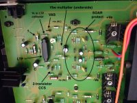
I tried to find a photo of the NAP150 that Klaus may have been referring to. And I found the attached which I've labelled up. You can see it's the familiar Naim schematic. Differences from my circuit is the inclusion of the output protection, the use of a 2-transistor CCS instead of BJT + 2 diodes.
Interestingly it looks like it has an RC decoupled + and - supply rails which is how I labelled it. But maybe not, the two capacitors labelled 'C' could be the input cap and feedback shunt cap. Not sure what's the exact detail.
The polystyrene cap that I think Klaus was curious about is labelled "?".
Attachments
Last edited:
Those "rails" are ground lines. The LTP CCS is higher at some 3.3mA. The Cs are indeed input and fb shunt (note they are correctly polarized!). The ? cap is an extra input filter: it has 21k to gnd from the input cap, then 4.7k to a 470pF then a 1k to the ? cap. The collector resistor is 270 ohms (lower than the NAP140 1k because the LTP current is higher).I tried to find a photo of the NAP150 that Klaus may have been referring to. And I found the attached which I've labelled up. You can see it's the familiar Naim schematic. Differences from my circuit is the inclusion of the output protection, the use of a 2-transistor CCS instead of BJT + 2 diodes.
Interestingly it looks like it has an RC decoupled + and - supply rails which is how I labelled it. But maybe not, the two capacitors labelled 'C' could be the input cap and feedback shunt cap. Not sure what's the exact detail.
The polystyrene cap that I think Klaus was curious about is labelled "?".
Be aware that the NAP150 it isn't meant to have the best performance: the NAP250s use better parts.
Member
Joined 2009
Paid Member
Since we are investigating Naim tricks:
I remember few years ago I saw a Naim circuit (possibly their regulated supply schematic) that was shown with -ve rail about 0.7V-1V larger than the positive. My simple thought then was that it's just compensation for the Baxandall diode extra drop on the negative side and was there for symmetrical clipping.
Does anyone has information/confirmation about that?
Would it be only for better clipping, or it might be more underneath?
I've never seen other dual rail amplifier design with different supply rails.
- Status
- This old topic is closed. If you want to reopen this topic, contact a moderator using the "Report Post" button.
- Home
- Amplifiers
- Solid State
- TGM10 - based on NAIM by Julian Vereker