Why was my first Google hit for this a supplier in Brazil - it's all Portuguese? Are you buying from South America? Have you been laundering drug-money?For this project I was planning to use Fairchild FJL5215/4315...

I'll take a look at the datasheets. What about other semiconductors...like drivers?
Member
Joined 2009
Paid Member
I have limited myself, for drivers, to TO-126 parts. My favourite drivers currently (isn't it fashionable to keep changing one's mind) are the KSA1220/KSC2690 pair.
No exciting laundry at my side. I won't buy the Fairchild parts, they're not available from Digikey. I'm tempted by the Sanken parts because I like their logo
No exciting laundry at my side. I won't buy the Fairchild parts, they're not available from Digikey. I'm tempted by the Sanken parts because I like their logo
I think, with the BDY56's, as pictured in a former posting within this thread, he took the best he could get. A transition frequency of 10 MHz wasn't too bad in those days. For what I have the oversight, these BDY56's were the fastest devices of that power then, faster by far than most of their contemporaries.
Best regards!
2N5038 and 2N5039 were a bit faster for the time at 60MHz. These still appear to be available http://www.farnell.com/datasheets/1697676.pdf?_ga=1.84277209.1710790857.1473286752.
The MJL21194 that I used for my simulation is nominally a 4MHz device however in comparison to a BDY at the same current of 1A the MJL rises to over 7 MHz and the output graphs for hFE and output characteristics are very good.
Member
Joined 2009
Paid Member
I'm liking these Sanken devices. The fT is a respectable 60MHz (of course this spec. is rather silly for most of the data sheets because it's usually specified at currents that are much higher than the cross-over region that we are interested in). I like the broad rising hFE with output current, this has been found by several people to correlate well with good bass.
Attachments
I'm liking these Sanken devices. The fT is a respectable 60MHz (of course this spec. is rather silly for most of the data sheets because it's usually specified at currents that are much higher than the cross-over region that we are interested in). I like the broad rising hFE with output current, this has been found by several people to correlate well with good bass.
A pity there seems to be no SPICE model. I looked at the MJL3281 in the output stage - there is no difference in the plot of the output waveform for 10kHz square into 8 Ohms with 2uF in parallel and that for MJL21194.
With the same compensation capacitor values in play for both and the same RC input filter I expect there would be no change with 60 MHz devices either.
With faster transistors it should be safe to change the input RC filter to allow an increase in the frequency bandwidth to 100 KHz as Naim have done for their top models.
2N5038 and 2N5039 were a bit faster for the time at 60MHz. These still appear to be available http://www.farnell.com/datasheets/1697676.pdf?_ga=1.84277209.1710790857.1473286752.
The MJL21194 that I used for my simulation is nominally a 4MHz device however in comparison to a BDY at the same current of 1A the MJL rises to over 7 MHz and the output graphs for hFE and output characteristics are very good.
When did the BDY56's appear to the market? And when did the MJL21193/94's? I've just tried to compare the first ones to their contemporaries.
Where did you get the fT numbers of those 2N5038/39's from? Not from the Farnell datasheet, did you?
Best regards!
Last edited:
When did the BDY56's appear to the market? And when did the MJL21193/94's? I've just tried to compare the first ones to their contemporaries.
Where did you get the fT numbers of those 2N5038/39's from? Not from the Farnell datasheet, did you?
Best regards!
Two sources - Towers International Transistor Selector - Revised Edition Update 1 issue 1977 and RCA Power Devices Handbook (July 1978).
In the latter 2N5038, 2N5039, 2N6354, 2N6496 are described as High-Current, High-Power, High Speed N-P-N Power Transistors Devices for Switching and Amplifier Circuits in Industrial and Commercial Applications. The fT peak value is 80 MHz at 2A.
2N5038 or 2N5039 - possibly both was or were also made by Motorola (and stocked by their local agent in the 70's and 80's).
I think BDY56's were available in the early 70's - Towers credits the maker as SESCOSEM in France.
MJL21194 -perforated emitter is more recent technology - post 1990 I think.
Member
Joined 2009
Paid Member
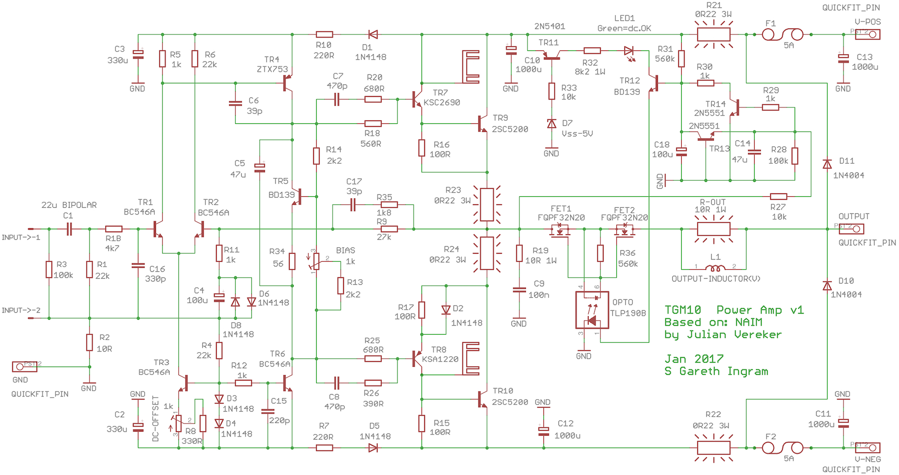
Why you need a electrical circuit C7/R20 (C10/R26)?
These different circuit C7/R20 (C8/R26) for Naim amp! Why?
I included them in my design so that the pcb had the footprint for these components. At the time I designed the pcb I thought they were important for the loop stability.
I have been thinking about these parts for awhile and I'm still not sure what their key function is for. These networks come in to play when the impedance of the capacitors becomes comparable with the series and parallel resistance - around 0.5MHz. Hence they have negligible impact on the audio frequencies.
Naim, or the designer Julian, have not published an explanation. People have theorized that these networks are designed to adjust the relative phase of the signal between the upper and lower outputs to achieve better alignment at cross-over. Two things cast doubt on this idea, firstly you wouldn't need phase shift on both upper and lower but just one of them, secondly is the negligible influence on signals at the frequency of interest. However, the unity gain bandwidth of the amplifier is quite high and good behaviour at high frequencies is still desired.
I have thought about perhaps it is to adjust for loading on the VAS, to smoothen out the impact of the output stage switching but simulations don't show much benefit.
I have thought about perhaps it is to help control minority charge carrier storage in the output drivers but cross-conduction is a concern for the output devices not the drivers.
I have thought about loop stability and I didn't find anything in simulations to suggest these networks are important. I have not explored parasitics such as inductive emitter resistors on the output devices or difficult speaker loads (Naim were into electrostatic speakers).
Last edited:
Member
Joined 2009
Paid Member
A pity there seems to be no SPICE model. I looked at the MJL3281 in the output stage - there is no difference in the plot of the output waveform for 10kHz square into 8 Ohms with 2uF in parallel and that for MJL21194.
I think it's doubtful that there will be any significant difference between competent output devices. Now, I happen to like the Sanken logo. This probably doesn't have much influence on the electrical performance though
Did you simulate with a purely resistive load or a speaker equivalence network including cross-over ? The real life performance will be influenced by the varying complex load that the speaker presents to the amplifier, including the cable.
I think that's a red herring....this has been found by several people to correlate well with good bass.
The way we perceive good/bad/clear/warm/cold, bass/mid/trebble, detail/soundstage/prat are not so simply correlated like that that you can draw a reliable conclusion.
But liking the label is real enough.
Member
Joined 2009
Paid Member
I think that's a red herring.
It's certainly a subjective thing. I remember reading about this opinion from another member on this forum who has build a lot of amplifiers both tube and SS. When I designed my TGM8 with BJT outputs I included a pair of Class C operating MOSFETs to provide strong defence against beta-droop. That amplifier has the best bass I've heard from any amplifier at any time. Others seem to like it too. Of course there are other factors at play and life is too short to become an expert on it.
Thank you!I included them in my design so that the pcb had the footprint for these components. At the time I designed the pcb I thought they were important for the loop stability.
I have been thinking about these parts for awhile and I'm still not sure what their key function is for. These networks come in to play when the impedance of the capacitors becomes comparable with the series and parallel resistance - around 0.5MHz. Hence they have negligible impact on the audio frequencies.
Naim, or the designer Julian, have not published an explanation. People have theorized that these networks are designed to adjust the relative phase of the signal between the upper and lower outputs to achieve better alignment at cross-over. Two things cast doubt on this idea, firstly you wouldn't need phase shift on both upper and lower but just one of them, secondly is the negligible influence on signals at the frequency of interest. However, the unity gain bandwidth of the amplifier is quite high and good behaviour at high frequencies is still desired.
I have thought about perhaps it is to adjust for loading on the VAS, to smoothen out the impact of the output stage switching but simulations don't show much benefit.
I have thought about perhaps it is to help control minority charge carrier storage in the output drivers but cross-conduction is a concern for the output devices not the drivers.
I have thought about loop stability and I didn't find anything in simulations to suggest these networks are important. I have not explored parasitics such as inductive emitter resistors on the output devices or difficult speaker loads (Naim were into electrostatic speakers).
I thought this high-frequency correction. This circuit for stability of the amp, but the amp is stable without circuit C7/R20 (C8/R26).
I think it's doubtful that there will be any significant difference between competent output devices. Now, I happen to like the Sanken logo. This probably doesn't have much influence on the electrical performance though
Did you simulate with a purely resistive load or a speaker equivalence network including cross-over ? The real life performance will be influenced by the varying complex load that the speaker presents to the amplifier, including the cable.
An 8 ohm resistor with 2uF in parallel - as I said in previous posts. The British Hi-Fi magazine that drew attention to Naim amplifiers and got their ball rolling, published 'scope shots of the waveform that resulted in that test.
I had the issue but there is only so much space that one cannot keep a magazine collection dating back 40 years.
Vereker claimed he tested his amplifiers on a variety of awkward test loads devised by himself and was concerned about latch up which he termed "loss of information". This can be avoided by stopper resistors in the driver base feed but the capacitance in the driver transistors has to be considered.
The PNP driver transistor is a common emitter amplifier - at high frequencies NPN and PNP transistors are less of a good match and in the latter case there will be some variable Miller Effect adding to the delay.
The phase correction networks ( as Vereker described them) are not used in the low power Nait amplifiers which used the same general structure using 5 MHz fT output transistors.
A lot of people liked and still like these and the clones that are around. The real deal items are collectable - they were a budget conscious entry point to the Naim hierachy.
In a different approach Linsley-Hood added a 22nF capacitor in parallel with the Baxandall diode to simulate the effect of the output transistor forward junction capacitance in his amplifier articles published in Hi-Fi News - November 1972 to January 1973. Linsley-Hood mentions phase correction networks in his writings.
SPICE simulations will indicate if a circuit will run into problems or not. The effect of changing the RC input filter will be subtle - I see that as the fun part of experiencing what, if any difference, changing that makes to ones perception of the music.
There are articles you can look up on line for interviews with Julian Vereker and come to your own conclusions from the ways he described his approach.
Member
Joined 2009
Paid Member
I've read around quite a bit but nothing firm on the phase networks. Spice shows them to have negligible effect. But Spice does show a much stronger and clearer effect from the input filter, the output zobel and feedback phase lead.
I've yet to see a good reason for the phase networks from Spice. That leaves measurement as an option.
---
Does anybody see benefit in using a NAIM style 4-pin DIN for the signal input ?
I'll include an RCA anyhow.
I've yet to see a good reason for the phase networks from Spice. That leaves measurement as an option.
---
Does anybody see benefit in using a NAIM style 4-pin DIN for the signal input ?
I'll include an RCA anyhow.
I think BDY56's were available in the early 70's - Towers credits the maker as SESCOSEM in France.
MJL21194 -perforated emitter is more recent technology - post 1990 I think.
Thank you! You got the point. Comparing two devices with about three decades of development between them is like comparing apples with oranges.
And thanks also for the manufacturer I've been searching for some posts ago.
Best regrads!
2N5038,2N5039
It is not clear if this is about BDY56 or 2N5038, 2N5039 Multicomp devices from Element14/Farnell/Newark - who in any case buy from reputable companies.
Assuming the latter - the Multicomp datasheet is less comprehensive than the RCA handbook which has more graphs -such as that for "Typical gain product bandwith (fT)"
In table of parameters, in the handbook there is one labelled [hfe] Magnitude of Small Forward Current Transfer ( IC =2A.dc Vce=10V, f=5MHz). The value is 12 and multiplying by f gives 60MHz.
The third block on page 2 of the Multicomp data sheet "Dynamic Characteristics" gives the same value of 12 under the same operating conditions.
I don't see any problem with using these. If anything, due to improved processing techniques, these could well be better than the originals.
Thank you! You got the point. Comparing two devices with about three decades of development between them is like comparing apples with oranges.
And thanks also for the manufacturer I've been searching for some posts ago.
Best regrads!
It is not clear if this is about BDY56 or 2N5038, 2N5039 Multicomp devices from Element14/Farnell/Newark - who in any case buy from reputable companies.
Assuming the latter - the Multicomp datasheet is less comprehensive than the RCA handbook which has more graphs -such as that for "Typical gain product bandwith (fT)"
In table of parameters, in the handbook there is one labelled [hfe] Magnitude of Small Forward Current Transfer ( IC =2A.dc Vce=10V, f=5MHz). The value is 12 and multiplying by f gives 60MHz.
The third block on page 2 of the Multicomp data sheet "Dynamic Characteristics" gives the same value of 12 under the same operating conditions.
I don't see any problem with using these. If anything, due to improved processing techniques, these could well be better than the originals.
I've read around quite a bit but nothing firm on the phase networks. Spice shows them to have negligible effect. But Spice does show a much stronger and clearer effect from the input filter, the output zobel and feedback phase lead.
I've yet to see a good reason for the phase networks from Spice. That leaves measurement as an option.
---
Does anybody see benefit in using a NAIM style 4-pin DIN for the signal input ?
I'll include an RCA anyhow.
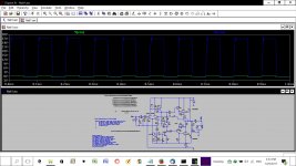
I deleted the phase networks in a reworked circuit - simulated with 10kHz square wave with output into 8 ohms with 2uF in parallel.
With MJL21194 output devices there is a continuous row of fuzz at the top and the bottom of the square wave.
With MJL3281's there is a spike at the top leading edge. Increasing the standing current by a factor of 10 effected no change. See attached.
Naim have sockets that allow a choice of connector DIN/RCA for the same input source.
Attachments
Member
Joined 2009
Paid Member
That's interesting !
Yes, those are ugly waveforms. Are you implying that the problem goes away when you put back the phase networks ?
Yes.
- Status
- This old topic is closed. If you want to reopen this topic, contact a moderator using the "Report Post" button.
- Home
- Amplifiers
- Solid State
- TGM10 - based on NAIM by Julian Vereker