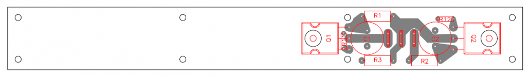
No. Didiet's original layout was taken and corrections made. The errors lay in the pin arrangemt of the signal transformers. All else stayed the same. Mirrored are difficult, if not impossible. If there is a specific layout issue that someone has noticed that they believe will contribute to some negative outcome, now is the time. Corrections will be made and sent to store for them to move forward. I do not have the experience to create a professional layout. If there are seasoned folks who can help make for a better layout, it would be a great service to the forum for them to offer advice.
Did my mistake on pin 2, 3, 6 and 7 ?
I'm really sorry
I must be said that the PCB has been totally stable and the layout of everything else was great, with no issues. ")
I believe the confusion comes from the diagram on the Jensen datasheet - it's not obvious if it's a top layout or a solder side diagram.
Your work on this project has been completely invaluable and I am sure there would not be a PCB for the diyAudio community without your contribution.
I believe the confusion comes from the diagram on the Jensen datasheet - it's not obvious if it's a top layout or a solder side diagram.
Your work on this project has been completely invaluable and I am sure there would not be a PCB for the diyAudio community without your contribution.


I do not want to step on anyones toes, and I highly appreciate all the great work already done and contributed for the F6 community. Im sure the PCB on the OP is good enough for the majority.
This is just an idea how to organise the PCB in a way that one can be used for both left and right channels and still achieve perfect symmetry inside the enclosure. It is not ideal and far from perfect. It is just an idea...
The drawing shows only the output stage, but tracing the transformer and the rest of the components should be easy. This is the top layer. Rest of the tracks would obviously be on the bottom layer...
What I am thinking here is that the gate resistors actually are on the gates. Feedback is taken from the output and about equal impedances on the tracks.
And, just 1 PCB for both channels for those perfectionists who bother about unequal stereoimage or performance between their super hi-end speakers in their perfect room acustic listening environment, or something...
Attachments
I didn't think minor differences in PCB traces made an audible difference? But who knows? Fanatics can use two of the same boards and mount one upside down. I say do it similar to Nelson's layouts with plenty of space between the outputs. Mounting outputs under PCB seems like a bad idea.
Mounting outputs under PCB seems like a bad idea.
Yes, definitely a drawback...
Experience on that, if fet blows it fries the PCB with it (if tightly clamped between the pcb and the heatsink). Better to use 6mm PCB stands to have min.1mm clearance between the fet and the pcb.
What else makes it a bad idea?
And,
a small change can make a big difference and,
I think Nelsons amp deserves the best possible PCB, dont you???
Please do not misinterpret I do not mean any offence!
As the PCB is not ready yet, may be there is still room for some minor improvements, if not, as said, Im sure it is good enough for the majority as is.
I think FETs under the PCB in a Class A amp thermally stresses the PCB and components on it.
I imagine using the production F6 as an example will get it close enough for most audiophiles. Anyone who's still not satisfied can build mono blocks or a stereo amp using two of the same boards and put the connections for one channel on the front.
F6 availability
I have decided to build one of these amps after some advice from other members (thank you!). My question is how do I go about pre ordering boards, transformers and the universal power supply board so I don't miss out on one of these beauties.
I must be said that the PCB has been totally stable and the layout of everything else was great, with no issues.
I believe the confusion comes from the diagram on the Jensen datasheet - it's not obvious if it's a top layout or a solder side diagram.
Your work on this project has been completely invaluable and I am sure there would not be a PCB for the diyAudio community without your contribution.
I have decided to build one of these amps after some advice from other members (thank you!). My question is how do I go about pre ordering boards, transformers and the universal power supply board so I don't miss out on one of these beauties.

Deep bass can sound little muddy, but I do mean deep. Stand up bass, kick drum, and the like are nice. I would imagine some electronic music or hip hop would make for an interesting show, but I choose to believe no one is listening to hip hop on F6
1.2 is spec'd, I believe, but why not more.
1.2 is spec'd, I believe, but why not more.
- Home
- Amplifiers
- Pass Labs
- The diyAudio Firstwatt F6